
Reducing Relay Power Consumption

The circuit utilizes a simple microcontroller or a basic timer IC to manage the operation of four relays in a predetermined sequence. The design incorporates a series of output pins from the microcontroller, which are connected to the relay control inputs. Each relay can be activated or deactivated based on the logic levels provided by the microcontroller.
For instance, a 555 timer configured in astable mode can generate a square wave signal, which can be fed into the microcontroller. The microcontroller can be programmed to respond to this signal by turning on each relay in succession, with a defined delay between each activation. This sequence can be easily modified through software, allowing for flexibility in operation.
The relays used in the circuit should be rated appropriately for the load they will control, ensuring they can handle the required voltage and current without failure. Additionally, flyback diodes should be placed across the relay coils to protect the microcontroller from voltage spikes generated when the relays are de-energized.
Power supply considerations are also crucial. The circuit should be powered by a stable voltage source that meets the requirements of the microcontroller and relays. Proper decoupling capacitors should be included to minimize noise and ensure reliable operation.
This design highlights the efficiency of using a microcontroller or timer IC for simple relay control tasks, demonstrating that complex systems are unnecessary for straightforward applications.This circuit proves that microcoprocessors, PCs and the latest ultra-accurate DACs are overkill when it comes to controlling four relays in sequence in re.. 🔗 External reference
Related Circuits
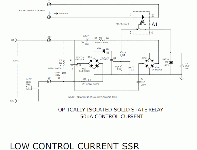
This circuit requires a control current that is 100 times smaller than that required by standard optically isolated solid-state relays. It is particularly suitable for battery-powered systems. By utilizing a combination of a high-current TRIAC and a very sensitive...
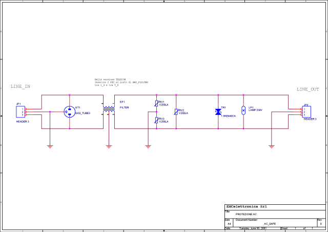
What is a circuit breaker? When is an AC power line filter or a phone line filter necessary? How can a noise filter be designed? Is it possible to create a homemade surge protector? The following circuit protection options...
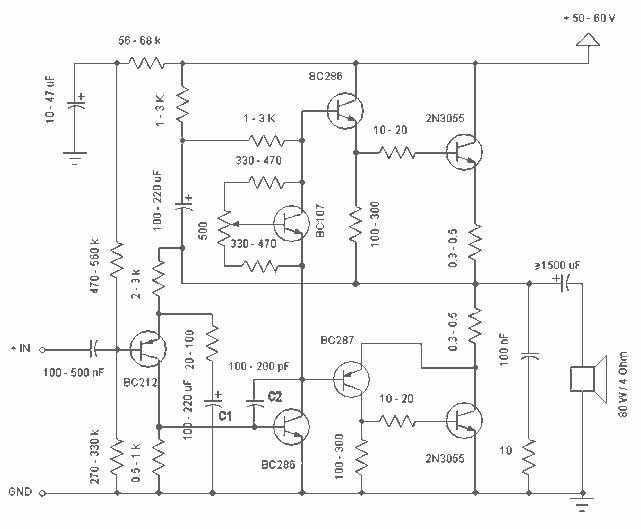
Simple and low cost. The optimal supply voltage is around 50V, but this amp works from 30 to 60V. The maximal input voltage is around 0.8 - 1V. As you can see, in this design the components have a...
A power supply circuit for the Sega Game Gear, intended for inclusion in your circuit collection. A more detailed explanation can be found on the website. The power supply circuit for the Sega Game Gear is designed to provide the...

Another method of using opamps to regulate a power supply is shown below. The power transformer requires an additional winding to supply the op-amps with a bipolar voltage (+/- 8 volts), and the negative voltage is also used to...
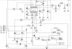
R2 sets the output voltage. The maximum current is determined by the value of R3: the over-current protection circuitry inside the LM723 senses the voltage across R3 and starts shutting the output stage off as soon as this voltage...