
Small Variable Power Supply

The circuit described involves the use of an LM723 voltage regulator, which is a versatile component commonly used for power supply applications. In this configuration, resistor R2 is critical in determining the output voltage of the regulator. By selecting an appropriate value for R2, the desired output voltage can be achieved as per the voltage divider rule in conjunction with the internal reference voltage of the LM723.
Resistor R3 plays a pivotal role in the current limiting feature of the circuit. The over-current protection mechanism is built into the LM723, which monitors the voltage across R3. When the voltage across R3 approaches 0.65 V, the internal circuitry of the LM723 detects this condition and initiates a shutdown of the output stage. This action prevents excessive current from flowing through the load, thereby protecting both the power supply and the connected components from damage due to overcurrent conditions.
The maximum allowable current through R3 can be calculated using Ohm's Law. Specifically, the current (I) can be expressed as I = 0.65 / R3. This means that, regardless of the load conditions, the current will not exceed this calculated value, ensuring safe operation even in the event of a short circuit at the output.
This design is particularly useful in applications where load conditions may vary significantly, and protection against overcurrent is necessary. The LM723's ability to regulate voltage while simultaneously providing over-current protection enhances the reliability and robustness of the power supply circuit. Proper selection of R2 and R3, along with appropriate heat sinking and component ratings, will ensure optimal performance of the circuit under various operating conditions.R2 sets the output voltage. The maximum current is determined by the value of R3: the over-current protection circuitry inside the LM723 senses the voltage across R3 and starts shutting the output stage off as soon as this voltage approaches 0.65 V. This way the current through R3 can never exceed 0.65/R3, even if the output is shorted. 🔗 External reference
Related Circuits
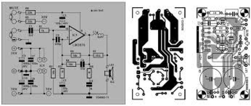
The air-cored inductor L1 is constructed using 13 turns of 1mm diameter enamelled copper wire, featuring an inner diameter of 10mm. The completed inductor is positioned over R7, with its terminals soldered to those of the resistor. All electrolytic...
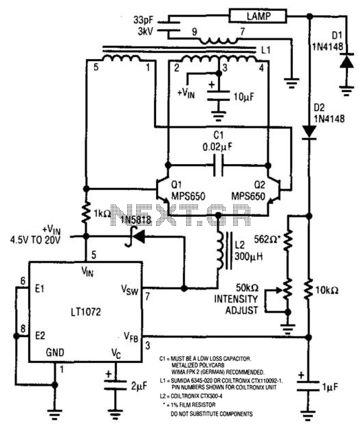
For backlit LCD displays, this supply will drive a lamp. The LT1072 drives Q1 and Q2, while a sine wave appears across C1. L1 is a transformer that steps up this voltage to approximately 1400 V. D1 and D2...
The core component of this controller is a switch mode voltage converter. L1 is responsible for converting voltage, while Q1 acts as the switch that controls the current flowing through L1. The switch mode voltage converter operates by rapidly switching...
This article provides a comprehensive overview of the methodology used for testing power supplies (PSUs) in three main sections. The first section outlines the PSU parameters that are evaluated and specifies the testing conditions. The second section defines commonly...
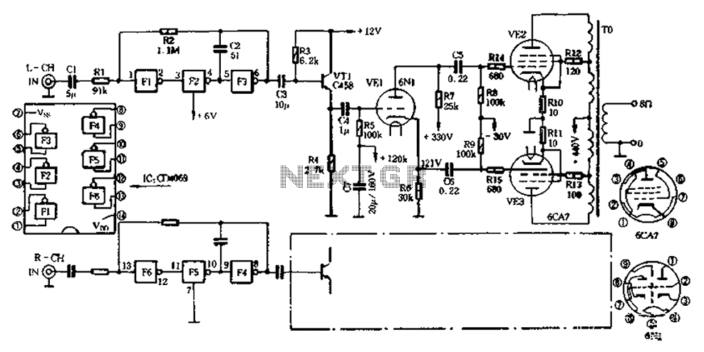
The CD4069 unit structure depicted in Figure 2-5 (a) consists of two abutment surfaces incorporated into a CMOSFET configuration. The input-output characteristics are illustrated in Figure 2-5 (b). Due to its superior unit switching curve, the CD4069 can be...
WARNING: Do not touch any part of the circuit when it is running (connected to the power line); this circuit is not isolated from the mains supply. This circuit operates directly connected to the mains supply, which poses a significant...