
Solid State Relay Required Only 50uA Drive Current

The described circuit is designed to operate efficiently in environments where minimizing control current is critical, such as in battery-operated devices. The use of a high-current TRIAC allows for the handling of significant power loads, while the sensitive low-current SCR ensures that the control requirements are minimal. This combination not only enhances the efficiency of the circuit but also extends the life of the power source, making it ideal for applications where energy conservation is paramount.
The circuit achieves full isolation, which is essential in protecting sensitive components from voltage spikes and transients that may occur in the load circuit. The transient protection feature is vital for safeguarding against potential damage caused by sudden changes in current or voltage, which can be common in inductive loads.
In practical applications, this circuit can be employed in various scenarios, including remote control systems, automation in industrial settings, or any application where reliable power control is necessary without compromising on safety or efficiency. The design should incorporate appropriate heat dissipation mechanisms for the TRIAC and SCR to ensure stable operation under high load conditions. Additionally, careful consideration of component ratings and circuit layout will further enhance the reliability and performance of the overall system.This circuit demands a control current that is 100 times smaller than that needed by a typical optically isolated solid state relays. It is ideal for battery-powered systems. Using a combination of a high current TRIAC and a very sensitive low current SCR, the circuit can control about 600 watts of power to load while providing full isolation and
transient protection. 🔗 External reference
Related Circuits
Sur ce site, il est possible de trouver des contributions dans des domaines d'intérêt variés. Il est également possible de suivre l'auteur sur Twitter : @davbucci. Le site est constitué de contributions hétérogènes. L'accès se fait via les liens...
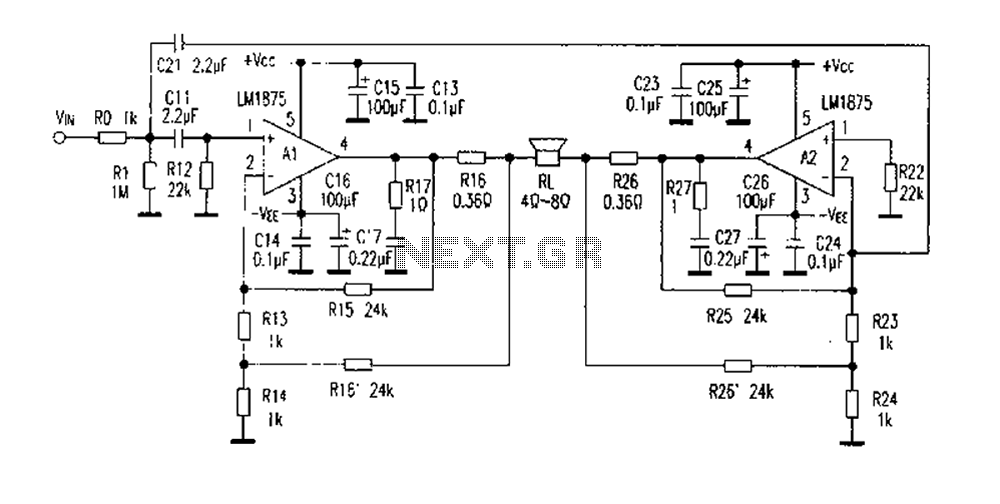
The DC current negative feedback BTL circuit illustrated in Figure 2 eliminates the standard BTL circuit capacitors C12 and C22, which affects the DC characteristics of the circuit. Resistors R16 and R26 function as sampling resistors, while R15, R16,...
The wide-range current pump for the precision phase-locked loop (PLL) circuit is a semi-precision circuit that provides an output current proportional to -V1, with a variation of approximately 10 to 15%, across a three-decade range. The 22 MΩ resistors...
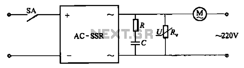
The circuit illustrated in Figure 3-13 is an RC surge absorption circuit that includes a resistor (R) and zinc oxide varistors (such as MY31, MYH12, MYH20 types, etc.), which serve as an overvoltage protection device. The resistance R is...
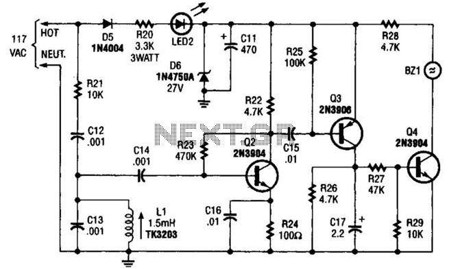
The baby-alert receiver consists of three transistors: Q2, configured as a high-gain linear amplifier; Q3, functioning as both an amplifier and detector; and Q4, which operates primarily as a switch. Additionally, there are several other components involved. The system...
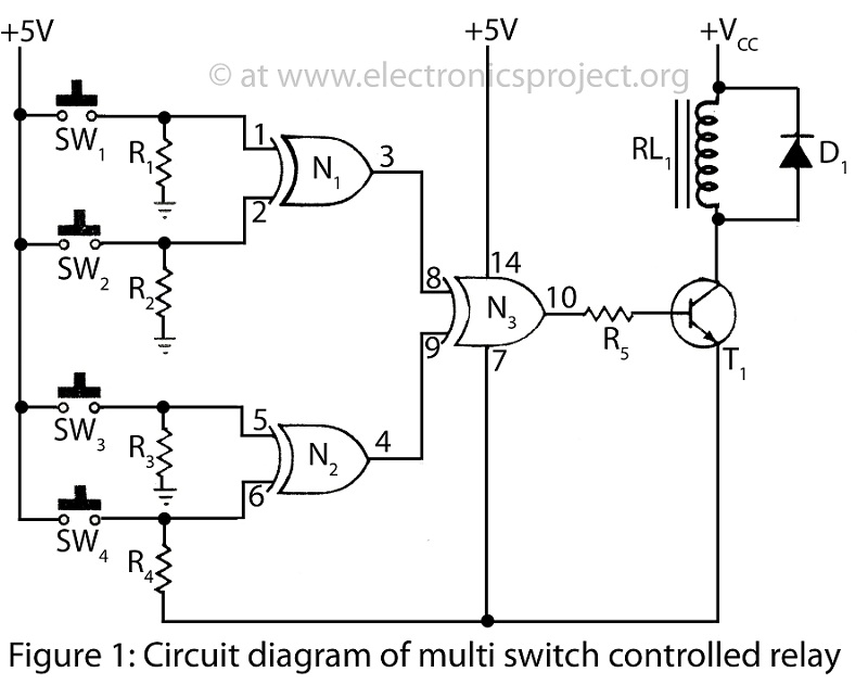
A Multi Switch Controlled Relay circuit is utilized to manage home appliances, featuring a circuit diagram that outlines the application of a multi switch-controlled relay using a single integrated circuit (IC) for various control functions. The Multi Switch Controlled Relay...