
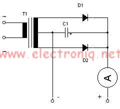
240 110V voltage converter circuit diagram

The AC voltage converter circuit typically employs a step-down transformer, which is the core component responsible for reducing the voltage from 240V to 110V. The transformer consists of two coils of wire, known as the primary and secondary windings. The primary winding is connected to the 240V AC supply, while the secondary winding outputs the reduced voltage of 110V AC.
In addition to the transformer, the circuit may include a fuse for overcurrent protection, ensuring that any excess current does not damage the circuit or connected devices. A rectifier may also be included if the application requires converting the AC voltage to DC voltage after stepping down, which involves diodes that allow current to flow in only one direction, effectively converting alternating current to direct current.
Moreover, filtering capacitors can be added to smooth out the output voltage, reducing ripple and providing a more stable supply for sensitive electronic devices. The circuit design may also incorporate a voltage regulator to maintain a consistent output voltage, regardless of fluctuations in the input voltage or load conditions.
The layout of the circuit should ensure proper insulation and safety measures, as working with high voltage AC power poses significant risks. Adequate spacing between components and the use of appropriate-rated materials are essential to prevent electrical hazards.
In summary, this AC voltage converter circuit is designed to efficiently step down 240V AC to 110V AC, making it suitable for powering various electrical devices that require a 110V supply. Proper design considerations, including protection, voltage regulation, and safety, are critical for reliable operation.Using this circuit diagram, can be designed a very simple AC voltage converter, which converts the 240V AC power to a voltage of 110V. Circuit can be successfully used to power electrical devices that require a supply voltage of 110V. If su.. 🔗 External reference
Related Circuits
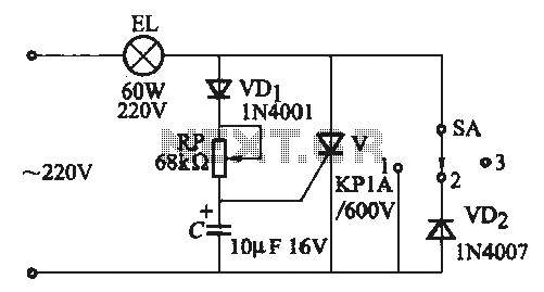
A thyristor-based incandescent dimming circuit is illustrated in Figure 2-66. Figure 2-66 (a) depicts a thyristor half-wave controlled dimmer combined with a diode approach. When switch SA is set to position "3," the adjustment potentiometer RP allows the voltage...
The alarm detector circuit operates differently from the Ultrasonic Alarm (1). In Ultrasonic Alarm (1), an alarm output is triggered by the detection of a reflected wave from an object during the setup time. Conversely, in this circuit, an...
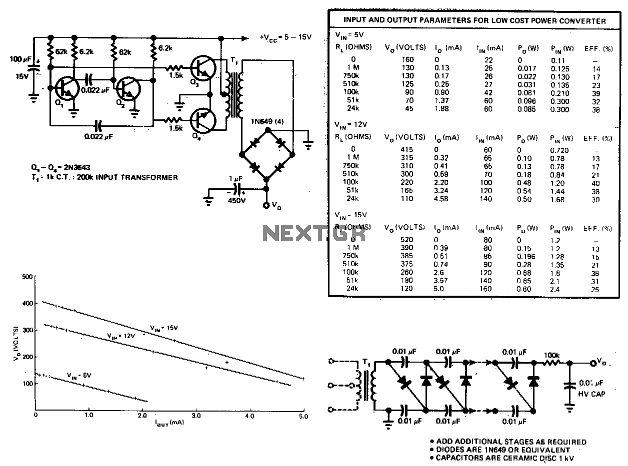
This circuit consists of an astable multivibrator driving a push-pull pair of transistors into the transformer primary. The multivibrator frequency should equal around 1 or 2 kHz. For higher DC voltages, voltage multipliers on the secondary circuit have been...
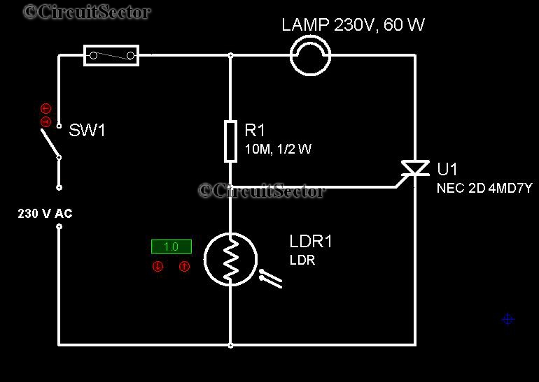
It is very convenient to automatically light a lamp in our absence during the evening when it gets dark. This automatic night lamp circuit can be utilized to illuminate staircase lights, porch lights, etc., automatically using a domestic power...
This simple lead-acid battery charger requires a center-tapped transformer (12V 0V 12V) capable of delivering a current of 5 amperes, two diodes, and one capacitor. To charge the batteries, the positive and negative terminals from the charger must be...
A bandpass filter allows a specific range of frequencies to pass while rejecting frequencies that fall outside the upper and lower limits of the passband. The frequencies that are permitted to pass are referred to as the passband, which...