
Refrigerator Alarm Circuit

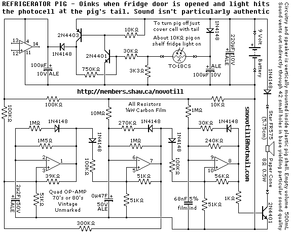
The described circuit functions as a light-sensitive alarm system for refrigerators, utilizing an LDR as the primary sensing element. The LDR decreases its resistance in response to ambient light, allowing the voltage at the junction of the LDR and R2 to rise. This voltage is used to charge capacitor C2 through R1, establishing a time delay before reaching the threshold voltage of operational amplifier U1. The time constant of the charging circuit can be adjusted by changing the resistance value of R1, which directly affects the responsiveness of the system.
Once the threshold is surpassed, U1 outputs a square wave signal that oscillates at a frequency determined by the RC time constant of the charging circuit. U2 serves to invert this signal, providing a complementary output that is necessary for the operation of U3, the tone oscillator. The tone oscillator generates a sound frequency that is typically used for alarm signals, enhancing the alertness of the system.
Importantly, when the LDR is not exposed to light, U3 remains inactive, conserving power. This feature is crucial for battery-operated devices, as it prolongs battery life. U4 amplifies the tone signal to a sufficient level to drive a ceramic transducer, which converts the electrical signal into an audible sound. The doubling of frequency at the transducer provides a more effective alarm sound, making it more noticeable.
The entire circuit is designed to operate efficiently with a standard 9-volt battery, making it suitable for portable applications. The low current consumption in standby mode ensures minimal drain on the battery, while the increased current draw during alarm activation allows for adequate sound output. This design is particularly beneficial for refrigerator applications, where monitoring for light exposure can indicate potential issues with the appliance, such as door openings or malfunctions.When the light falls on the LDR, it becomes low ohmic. The voltage at the junction of LDR/R2 charges the C2 via the R1 slowly. After about 10 seconds, the capacitor voltage reaches the input threshold of U1. Then U1 generates a square wave signal with a frequency of several Hertz. The time delay can be shortened by decreasing the value of R1 down to 220K ©. U2 inverts the signal from U1. This inverted signal switches the U3 tone oscillator. When there is no light hitting the LDR, U3 is turned off. Finally, U4 amplifies the tone signal generated by U2 and drives the ceramic transducer. The frequency is doubled at the transducer. The refrigerator alarm circuit can be powered with a small 9 volts battery. The current consumption is around 0. 6 mA at standby and 5 mA when the alarm is activated. 🔗 External reference
Related Circuits
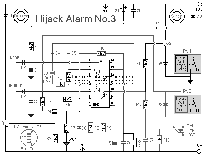
Upon opening your fridge door the photocell is exposed to light and the piggy oinks. Reverse engineered circuit diagram is of an early commercial design which uses an OP-AMP to make simulated pig sounds. Modern Fridge Pigs sound much...
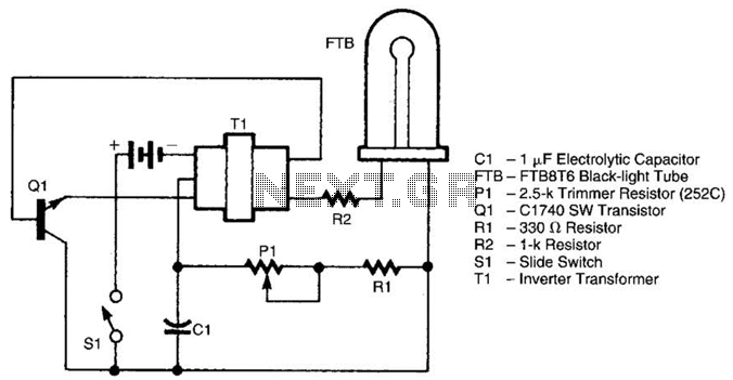
The Vehicle Anti-Hijack Alarm No3 is designed specifically for scenarios where a hijacker forcibly removes the driver from the vehicle. If any door is opened while the ignition is on, the circuit will activate. The Vehicle Anti-Hijack Alarm No3...
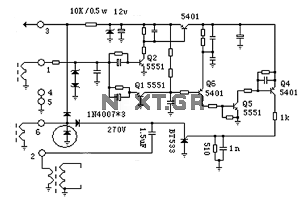
The battery-operated black light utilizes a U-shaped, unfiltered black-light tube, which requires approximately 250 Vac for operation. To generate the 250 Vac from a 6-V battery, the circuit employs a one-transistor blocking oscillator that drives a ferrite inverter transformer....
The anatomy of two ignition experiments revealed a common issue, specifically that both ends of the ignition coil are equipped with a diode. This design choice by manufacturers has implications for performance. The ignition coil generates a negative half-cycle...
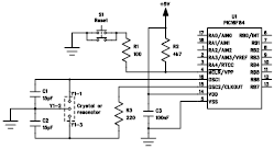
The following file contains detailed information about the design of a basic clock oscillator circuit diagram. Included in this file is information about selecting the components. The clock oscillator circuit is a fundamental component in various electronic systems, providing a...
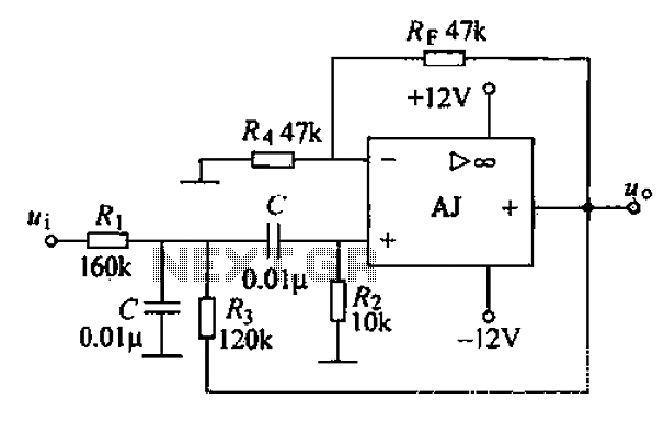
A band-pass filter permits only signals within a specified frequency range to pass through, while attenuating or suppressing those outside this range. This is characterized by a lower frequency limit and an upper frequency limit. A typical implementation is...