
Regenerative AM Receivers

The regenerative circuit operates by utilizing feedback to enhance signal strength, allowing for the amplification of weak radio signals. The oscillator's performance is contingent upon the precise configuration of the tapped coil and the tuning capacitor, which together form a resonant tank circuit. This tank circuit is critical for determining the oscillation frequency, which is typically set to match the frequency of the desired radio signal.
The gain control mechanism is achieved through the manipulation of feedback, which can be adjusted to achieve the desired level of oscillation. This adjustment is crucial, as it allows the user to stabilize the circuit and prevent it from entering a state of runaway oscillation. The feedback loop is formed by connecting a portion of the output signal back to the input through the tapped coil, which enhances the regenerative effect.
In terms of components, the choice of the small-signal NPN transistor is flexible, as many types can fulfill the requirements of the circuit. The transistor functions as the active element that amplifies the RF signal. The audio output stage, while capable of producing sound, typically requires additional amplification to drive higher loads such as headphones or speakers. This necessitates the integration of an audio amplifier stage, which can be selected based on power requirements and compatibility with the regenerative circuit's output.
Overall, the regenerative circuit is a versatile and experimental platform for audio and radio frequency applications, allowing users to explore the principles of oscillation and amplification with a range of readily available components.The regen is basically an oscillator circuit with a gain control that allows the user to adjust the feedback to a point just below oscillation or, quite often, just above the critical level such that a small oscillation is present. The typical regen uses a tapped coil or additional windings to connect into the tuning tank and the tuning capacitor
provides the total tank capacitance. The components are not critical and the values were pretty much the first ones found on the bench that were near the `right` value so don`t hesitate to experiment. The transistor could be just about any small-signal NPN including the 2N4401, 2N3904, 2N2222, or others.
The audio output is fairly weak and will need an amplifier to drive headphones or a speaker. See the audio amplifier page for suitable amps.
Related Circuits

The figure illustrates the schematic of the circuit, which features several unique characteristics that contribute to its reliable performance. To eliminate the tendency of regenerative receivers to radiate oscillator-frequency signals, a transistor buffer (Q1) is positioned between the antenna...

This project involves a Regenerative Receiver designed for the 80-meter Amateur band, with the capability to tune from approximately 3 MHz to 10 MHz, suitable for Shortwave listeners. It shares a design lineage with the previously created "40-Meter Tweeter."...
The regenerative detector uses a field effect transistor (FET). Like with the better valve designs, feedback is controlled by a variable capacitor. A ferrite rod was used to allow reception of local stations without an external antenna. This FET...
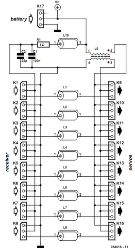
Receiver interference is a common issue among model builders. Preventive measures, such as ferrite beads fitted to servo cables, are frequently employed in larger models and electrically driven models to prevent the cables from acting as antennas and radiating...
Many radio amateurs are interested in powering simple radio receivers using "free energy," which refers to energy obtained directly from the air via the receiver antenna. The circuits described can facilitate radio reception through a loudspeaker. However, questions remain...

This project originated from an interest in a new form of radio transmission known as Digital Radio Mondial (DRM). The Digital Radio Mondial (DRM) is a revolutionary digital broadcasting technology designed for AM and FM radio. It provides enhanced audio...