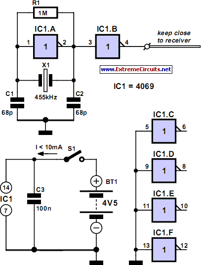
DRM Down-Converter For 455kHz IF Receivers
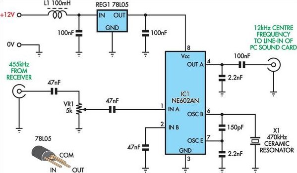
This project originated from an interest in a new form of radio transmission known as Digital Radio Mondial (DRM).
The Digital Radio Mondial (DRM) is a revolutionary digital broadcasting technology designed for AM and FM radio. It provides enhanced audio quality, improved reception, and additional features compared to traditional analog broadcasting. DRM operates in various frequency bands, including shortwave, medium wave, and VHF, allowing for versatile applications in different geographical areas.
In a typical DRM transmission system, an encoder converts the audio signal into a digital format, which is then modulated for transmission. The modulation process typically employs Orthogonal Frequency Division Multiplexing (OFDM), which is robust against multipath fading and interference, making it suitable for long-distance broadcasting. The transmitted signal can be received by DRM-capable receivers that decode the digital information, delivering high-quality audio and supplementary data services such as text information, images, and program schedules.
The implementation of DRM requires careful consideration of the transmitter design, including power output, antenna configuration, and bandwidth allocation. Additionally, the receiver design must incorporate advanced signal processing techniques to ensure optimal performance under varying reception conditions.
Overall, the adoption of DRM technology represents a significant advancement in radio broadcasting, providing listeners with a superior listening experience and broadcasters with enhanced capabilities for content delivery.This project came about due to my interest in a new form of radio transmission called DRM, which stands for Digital Radio Mondial.. 🔗 External reference
