
regenerative radio receivers

The regenerative radio receiver described is a sophisticated yet accessible project that combines various electronic components to enable effective signal reception across multiple bands. The architecture of the receiver is structured into three fundamental stages: the RF amplifier, the regenerative detector, and the audio amplifier, each serving a distinct purpose in the signal processing chain.
In the RF stage, the bipolar transistor (Q1) plays a critical role in amplifying incoming radio frequency signals from the antenna. This stage is crucial for enhancing weak signals and ensuring that the subsequent stages receive adequate signal strength for further processing. The isolation provided by the RF stage is essential to maintain the integrity of the received signals and to prevent unwanted feedback that could lead to oscillation issues in nearby receivers.
The regenerative detection stage, utilizing the JFET (Q2), is where the receiver's sensitivity is maximized. By employing positive feedback, this stage allows for the amplification of the RF signals while simultaneously demodulating the signal to retrieve the audio content. The regenerative action not only enhances sensitivity but also allows for improved selectivity, enabling the receiver to discern between closely spaced frequencies.
The audio amplifier stage, constructed with a low-cost integrated circuit, is responsible for converting the demodulated signals into audible sound. This stage typically includes additional filtering and amplification to ensure that the output is clear and intelligible for the listener.
Overall, the design of this regenerative radio receiver exemplifies a balance between simplicity and performance, making it an ideal project for amateur radio enthusiasts looking to deepen their understanding of radio technology while building a functional device. The project encourages collaboration and learning, providing an excellent platform for skill development in electronics and radio communication.A regenerative radio receiver is unsurpassed in comparable simplicity, weak signal reception, inherent noise-limiting and agc action and, freedom from overloading and spurious responses. The regenerative radio receiver or, even super-regenerative radio receiver or, "regen" if you prefer, are basically oscillating detector receivers.
They are simpl e detectors which may be used for cw or ssb when adjusted for oscillation or a-m phone when set just below point of oscillation. In contrast direct conversion receivers use a separate hetrodyne oscillator to produce a signal. In the comprehensive electronic project presented here, Charles Kitchin, N1TEV has provided us with a three stage receiver project which overcomes some of the limitations of this type of receiver, principally the provision of an rf amplifier ahead of the detector.
The radio described here is a two band short wave receiver which is both very sensitive and very portable. It receives AM, single sideband (SSB), and CW (code) signals over a frequency range of approximately 3.
5 to 12MHz. This includes the 80, 40, and 30 meter Ham bands plus several international short wave bands. This receiver is ideal for code practice and for general short wave listening although a certain amount of practice (and patience) is needed while the user learns how to tune and adjust the controls. This should be considered a medium skill level project. It was designed to be built by the average Ham under the mentorship of experienced "elmers" who can provide guidance on soldering, coil winding, troubleshooting, and operating the receiver.
It is also a good "family" project. In the BARS club class, several parents built radios with their kids. The BARS Ham Radio club was fortunate to have several experienced "Elmers" including club president Ken Caruso, WO1N, club treasurer Bruce Anderson, W1LUS, New England Vice ARRL Director Mike Raisbeck, K1TWF, and regenerative radio / homebrewing fanatic Chuck Kitchin, N1TEV. Many other members of the club helped out by donating parts or their time to this project. The majority of the kit builders were graduates of the Chelmsford Charter School summer Ham radio class and their dads.
However, the enthusiasm was widespread and several BARS members just had to build one too! Clubs planning to tackle a project like this should plan on a minimum of two sessions to complete the kits. You need to plan time to teach soldering techniques, component identification and schematic reading. This project is designed to be built using the FAR Circuits printed circuit board (the name of the PC board is the same as this project`s title).
The use of this board is HIGHLY recommended as it greatly reduces the time spent soldering the circuit and avoids the many wiring errors that always occur during construction. It also helps prevent crossed connections and provides better performance than a hand wired board (because proper component location and shielding are designed into the PC board).
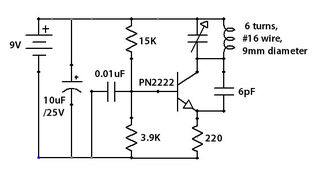
The PC boards are available from FAR Circuits for $5. 00 each plus $1. 50 shipping for up to 3 boards. There is a group discount rate of 10% for 10 boards or more. You can contact FAR Circuits at 18N640 Field CT. Dundee, IL, 60118-9269. Tel: 847-836-9148 (voice and FAX) EMAIL: Farcir@ais. net Orders NOT accepted by email. As shown in Figure 1, this receiver consists of three sections: a radio frequency RF stage, a detector stage, and an audio amplifier stage. A bipolar transistor is used in the radio frequency stage, a JFET in the detector and the audio amplifier uses a low-cost IC.
The RF stage, Q1 amplifies the antenna signals and provides isolation to prevent the radio`s oscillations from causing interference to other receivers in the area. JFET Q2 is a "regenerative" detector, which, by the use of positive feedback, greatly increases the receiver`s sensitivity.
It also supplies a local oscillation for the reception of CW 🔗 External reference
Related Circuits
If you're the sort who'd like to have an HF receiver in every room, but can't afford it, this idea is for you. It will also appeal to the beginner wishing to build the simplest possible direct conversion receiver....
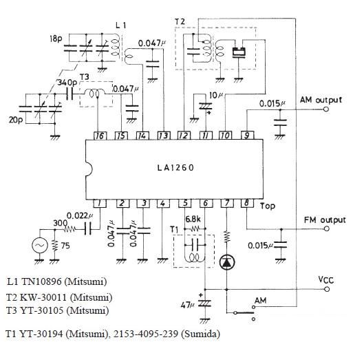
This FM IF MW radio receiver circuit schematic utilizes the LA1260 integrated circuit (IC), which is suitable for AM and FM radio receiver electronic projects. The LA1260 incorporates numerous functions and features essential for radio receiver applications, including a...
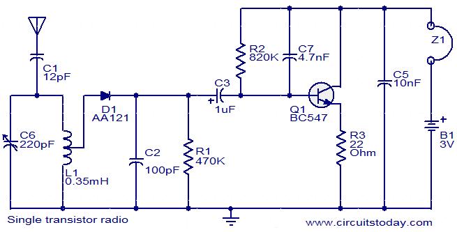
The circuit diagram of a simple radio that uses one transistor and a few other passive components. Component: Diode, Capacitor, Inductor, Resistor. The circuit design for a simple radio receiver typically incorporates a single transistor as the active amplification element,...
Later, the same pivot table will be utilized to list the parts for each of the eight phases in the build, organizing them into phase-specific bags of parts. The initial observation is that there are slight inconsistencies between the...
This is highly illegal. As a consumer, compliance with Part 15 of the rules and regulations is mandatory. Part 15 stipulates that a device must accept any interference it receives and must not cause harmful interference, such as jamming...

The FM radio receiver circuit is designed using the TDA7000 integrated circuit (IC). This circuit operates with a DC voltage range of 2 volts to 12 volts. The TDA7000 IC is specifically engineered for FM reception and employs a...