
Regulator circuit silicon resistor formed

The simple voltage regulator circuit is a fundamental component in power supply design, providing a stable output voltage from a varying input source. The silicon regulator, typically a Zener diode, operates in reverse breakdown mode to maintain a constant output voltage across the load. The resistor R, strategically placed in series with the regulator, is crucial for protecting the circuit from excessive current that could potentially damage the regulator.
In practical applications, the circuit is connected to a rectified and filtered DC voltage source, which may exhibit fluctuations due to variations in the AC mains supply or changes in the load. The regulator's ability to maintain a steady output voltage is critical for sensitive electronic components that require a stable power supply for proper operation.
The limitations of this circuit arise particularly under conditions of high load variation or significant input voltage changes. When the load current increases dramatically, the regulator may not be able to compensate adequately, leading to voltage drops that can affect the performance of connected devices. Similarly, if the input voltage exceeds the regulator's specifications, it may lead to overheating or failure.
To overcome these challenges, a series regulator can be implemented. This configuration allows for greater flexibility and improved performance by using an active component, such as a transistor, to regulate the output voltage continuously. The series regulator can adjust the voltage dynamically based on real-time load conditions, providing a more robust solution for applications requiring precise voltage regulation.
In summary, while the simple voltage regulator circuit serves as an essential building block in electronic design, its limitations necessitate the consideration of more advanced regulation techniques for demanding applications.By the regulator and the regulator circuit silicon resistor formed Simple voltage regulator circuit is mainly composed of silicon regulator with a resistor, as shown in FIG. FIG vocational DC voltage rectifier filter obtained, the regulator VDZ shame in parallel with the load, because the diode voltage = assume steady work when pressed, should reverse connection, so the regulator should be connected to the positive input into the negative terminal voltage. FIG resistor R is essential, it has two roles: one is to limit current after the reverse breakdown voltage regulator tube to prevent excessive damage to stop the current regulator, so called current limiting resistor R {which is the second is when the grid voltage fluctuations caused by input voltage (ie, rectifying the filtered output voltage) "changes by adjusting the voltage drop across R on to maintain the output voltage substantially constant.
However, the presence of two voltage regulator circuit projections disadvantages: one is when the change in grid voltage and load current is too large, the circuit can not be fit to be; the other is the output voltage can not be adjusted in order to improve the above shortcomings, may adopt a series regulator circuit.
Related Circuits
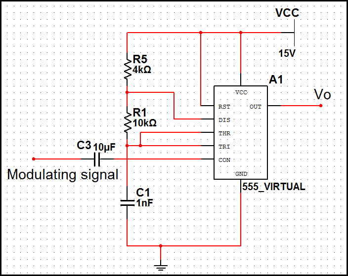
In pulse position modulation, the amplitude and width of the pulses are kept constant, while the position of each pulse with reference to the position of the reference pulse is changed according to the instantaneous sampled value of the...
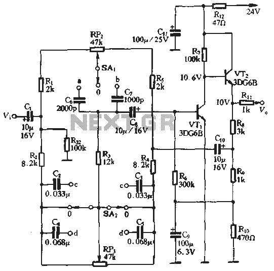
An attenuation switch is utilized to modify the pitch of a feedback control circuit's transition frequency, specifically for two treble controls. RP3 is designated for bass control, while SA1 and SA2 are employed to adjust the high bass control...
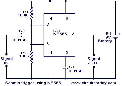
In addition to its timing functions, the two comparators of the 555 timer can be utilized independently for various applications. One such application is a Schmitt Trigger. The inputs of the two comparators (pin 2 and pin 6) are...
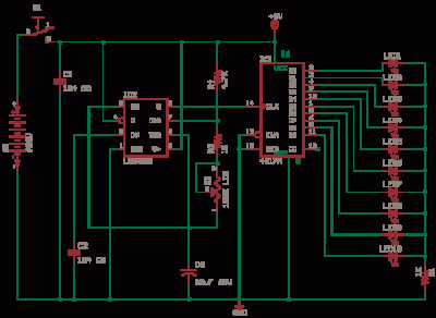
The 555 Astable generates a clock for this circuit, functioning as an oscillator that produces a square wave output at pin 3. This output is counted by the CD4017 decade counter, which creates a running lights effect. The CD4017...
This project is suitable for individuals who enjoy experimenting with electronics. It presents a low risk of damaging the unit. This project involves creating a simple electronic circuit that allows users to engage in hands-on experimentation without significant risk. The...
The conversion of a circuit from NPN to PNP configuration is in progress, along with a switch in polarity. Parts are being ordered for this modification. The conversion from an NPN to a PNP transistor involves several key changes in...