
A five inverter circuit

The self-excited transistor inverter circuit utilizes a feedback mechanism that allows it to maintain oscillation without requiring an external power source. The circuit typically consists of a few key components: transistors, resistors, capacitors, and a transformer. The transistors function as switches that alternate the current flow through the transformer, generating an alternating current (AC) output suitable for fluorescent lamp operation.
The feedback loop is established through a combination of resistors and capacitors, which help to stabilize the oscillation frequency and ensure that the inverter remains operational under varying input conditions. The transformer not only steps up the voltage to the required level for the fluorescent lamps but also provides isolation between the low-voltage control circuit and the high-voltage output.
In practical applications, the inverter is designed to handle input voltage fluctuations, making it ideal for environments where the power supply may be inconsistent. The circuit's simplicity allows for easy assembly and troubleshooting, making it accessible for both hobbyists and professionals in electronics. Overall, this self-excited transistor inverter circuit represents an efficient and reliable solution for powering fluorescent lighting systems.Self-excited transistor inverter circuit. These types of inverters better performance, but also relatively simple diagram 2-122, available for 8 ~ 40W fluorescent lamps. When the power supply voltage is within 20% of the soil changes, which can operate stably.
Related Circuits
A user has been experimenting with modifications to a budget-friendly MXL V67s microphone to enhance its performance, specifically aiming to improve the condenser quality until a higher-end model can be acquired. The MXL V67s is a popular choice among budget-conscious...
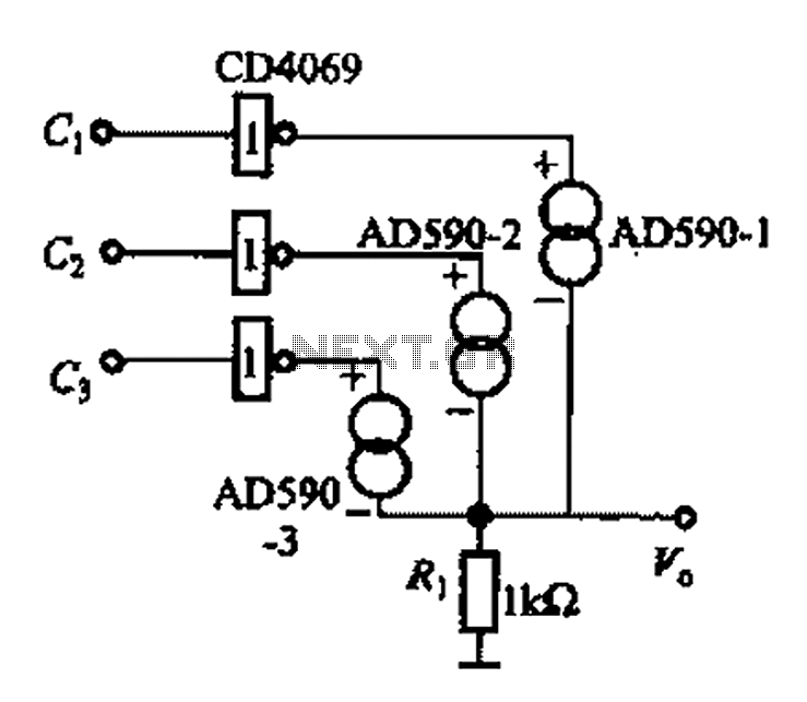
The AD590 is illustrated in a basic application circuit. As the AD590 provides a current output, a series resistance is used to convert this output current into a voltage. In the circuit, RP serves as the output voltage (vo)...
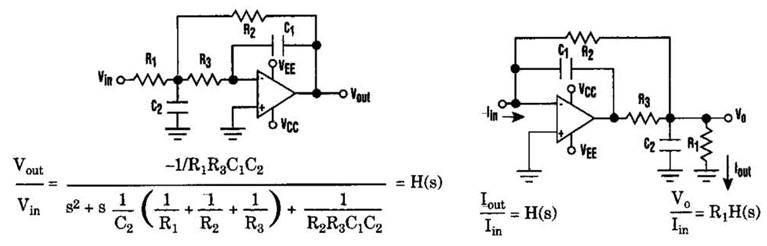
Current-Driven Sallen-Key Filter Circuit Diagram. The low-pass Sallen-Key filter is a staple for designers because it contains few components (A). The Sallen-Key filter is a widely used active filter topology that employs operational amplifiers (op-amps) to achieve desired filtering...
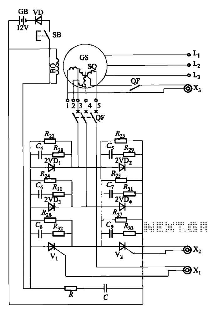
The setup is connected to separate stator windings of a harmonic generator, which leads to a thyristor rectifier supply for the third harmonic voltage, positioned after the motor field. The output voltage varies with changes in the winding harmonics...
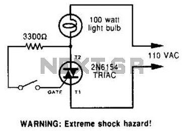
A triac can be utilized as a line-operated AC power switch that directly controls lamps, heaters, or motors. A brief current pulse into the gate activates the triac, and it remains on until the main current reverses. A triac, or...
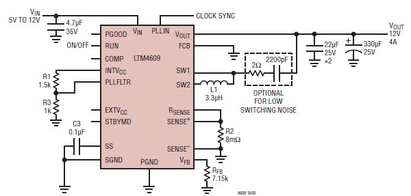
A very simple, high-efficiency switching mode buck-boost power supply circuit can be designed using the LTM4609 switching regulator IC. This circuit will provide a fixed output voltage of 12 volts. As illustrated in the schematic, the switching power supply...