
Relay Coil Energy Saver

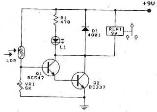
The described circuit addresses the issue of heat generation in relays due to prolonged energization. In typical applications, relays are used to control high-power devices, and when they are continuously energized, they can generate excessive heat, potentially leading to premature failure. The proposed circuit operates by initially energizing the relay to close the contacts, allowing current to flow to the load. After a predetermined time, the circuit reduces the hold current required to keep the relay in the energized state.
This is typically accomplished through the use of a resistor or a secondary control mechanism that modifies the current flowing through the relay coil after the initial actuation. The circuit may incorporate a timing element, such as a capacitor and resistor combination, or a dedicated timing IC, to provide a delay before the hold current is reduced.
The design must ensure that the relay remains in a closed position while the load is powered, even with the reduced current. This can be achieved by utilizing a latching mechanism or a relay with a low holding current specification. Additionally, it is essential to select a relay that can withstand the initial inrush current without damage and to calculate the resistance value for the hold current accurately to ensure reliable operation without risking relay dropout.
In summary, this circuit effectively manages the thermal characteristics of the relay during operation, enhancing reliability and longevity while maintaining functionality in controlling the connected load. Proper component selection and timing considerations are crucial in achieving the desired performance and preventing overheating.Some relays will become warm if they remain energized for some time. The circuit shown here will actuate the relay as before but then reduce the ‘hold cu.. 🔗 External reference
Related Circuits
Half of RL1 and RL2 manage the switching mechanism, while the other half connects to an application. The relays operate at 200 ohms above ground, with one terminal referenced to positive voltage, which deactivates them. RL1, when off, applies...
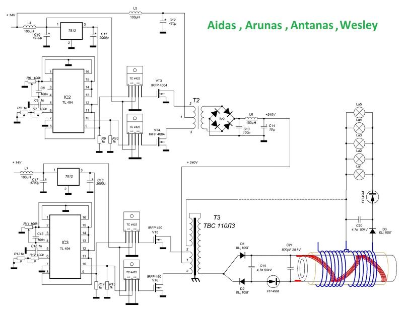
A circuit diagram has been found on a Russian website, freeenergylt.narod2.ru/Aidas. The diagram includes a pulse generator, which requires PCGU1000 equipment for the coils to function. There are discussions about the internal resonation design, involving a capacitor in parallel...
A small electronic switch connects a battery to equipment for a specific duration when a push-button is momentarily pressed. The circuit also considers ambient light levels; when it is dark, the display cannot be read, so it is logical...
All files are found using legitimate search engine techniques. This site does not condone hacking into sites to create the links it lists. It is assumed that all links found on the search engines used are obtained legally and...
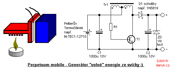
Introduction: This device is not a true perpetual motion machine or a source of free energy from the atmosphere; however, it presents an intriguing experiment, particularly for beginners and enthusiasts of alternative energy sources. It enables the generation of...
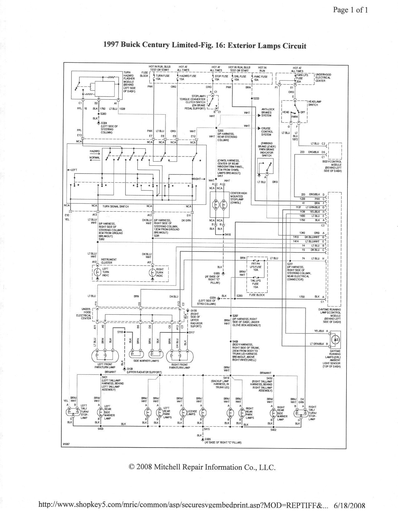
It is essential to ensure that none of the light bulbs on the vehicle are burnt out, particularly the turn signal lights, brake lights, and dashboard indicator lights. Malfunctions can occur when bulbs are burnt out. Utilizing the exterior...