
Selfrunning Free Energy 5 KW Kapanadze 1

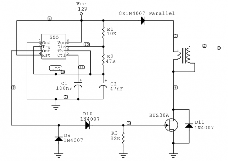
The circuit diagram in question is designed to function with a pulse generator, specifically utilizing the PCGU1000 equipment. This equipment is integral for driving the coils effectively, which are likely part of a resonant circuit aimed at achieving enhanced energy output. The design incorporates a capacitor connected in parallel to a portion of the high-voltage secondary winding, which is critical for internal resonation. This method is noted to be significant in the context of the circuit's operation, as it can influence the resonance characteristics and overall efficiency.
Replicating the original circuit design poses challenges, primarily due to the use of vintage components, which may not be readily available. The STAAAR group's implementation serves as a reference point, demonstrating the complexity and potential of such systems. The discussion also touches on the light intensity observed from different lamp types when powered by this circuit, indicating that variations in output can occur depending on the specific configurations and components used.
An additional aspect of the design involves the suggestion to add a second coil over the Katcher coil. This modification is proposed to enhance the system's performance by allowing the high-voltage negative to pass through the additional coil, potentially increasing the electromagnetic effects produced. This approach aligns with the principles of electromagnetic induction and resonant coupling, which are fundamental in achieving higher efficiency in energy transfer.
The STAAAR group's design features two Katcher-like coils, one connected to the control grid and the other to the tube's plate. This configuration is essential for maintaining proper phasing connections, which are critical for the intended operation of the circuit. The design also includes secondary Tesla coils that resonate at specific wavelengths, which, when modulated at 50Hz, can create a harmonic relationship among the frequencies produced. The internal air ionization promoted by the strong electric fields generated by the primary and secondary coils is considered a key factor in the circuit's overall effectiveness.
In summary, this circuit diagram represents a complex interplay of components that can yield significant results when appropriately configured. The focus on replicability and the exploration of coil configurations are vital for advancing understanding and application of these principles in practical scenarios.I found one circuit diagram, on one russian site, freeenergylt dot narod2 dot ru/Aidas. Question is, diagram contains something pulse generator, for this circuit diagram need PCGU1000 equipment, for functioning the coils?
my impression now is that casually you are on something: do you remember the stories about TV set reported by SM (?)...just about funny things happening with flybacks...we are on muddy terrain as, at least in your case, situation appears to be unrepeatable due to kind of internal secondary shorting you are experiencing...MAY BE THAT THE PARTIAL INTERNAL FUSING IS IN A WAY ENHANCING RESONATION, who knows?
Please do not forget that original basic #2 design provided for an 'internal resonation' putting a cap in parallel to a part of the HV secondary....and T-1000 clearly says that's particular & important. Unfortunately it is very difficult to replicate as the Russian unit the STAAAR group used is vintage TBC.
I agree that there could be OU source.
It could be interesting for me to have a rough idea on light intensity you see (for example: what kind of lamp, filament red, white, low shining....). In my case before Ventex neon power supply died I obtained white filament (low shining) on 240V/60W lamp.
Finally I reccomend to use solution easy replicable for every aspect as contrary impossible to have any confirmation.
"...Remember I mentioned to you to try and put a second coil over your Katcher coil, like @woopy did, but @woopy did not send the HV negative through that second coil and was still getting some great effects.
So look at the TK coil in your last posted diagram. There is not that much difference from that coil (L27 to L31) and your Katcher coil if it had a second coil wound over it to pass the HV-...."
I did not notice and neither did any action for putting additional coil on kacher and routing there also the Hv...but I can try it soon. Tnx for remembering.
I have also your same impression about last STAAAR group implementation. It is rather easy to understand that there are let's say 2 kachers-like coils: one connected to control grid and another one connected to tube's plate...all with proper phasing connections.
The design does provide also the secondary TC coils resonating at lambda and lambda/4 wavelength's...all mixed with 50Hz modulation. In output we should have 3 freqs f1 from TC#1, f2 from TC#2 in harmonic relationship and f3=50Hz). Coils internals air Ionization promoted by the huge electrical field by TC1 and TC2 big magnifier coils could really be the key factor.
I've almost finished the coil set (sse pic) and I'm now working on circuit while waiting for ordered components .
Related Circuits
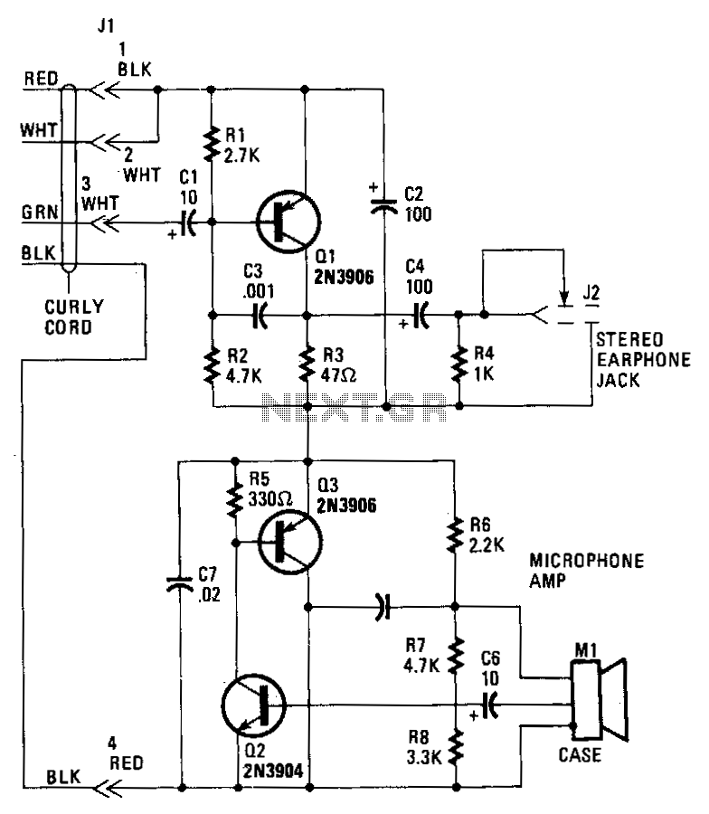
Transistor Q1 in the headset amplifier circuit amplifies the 30 mV signal intended for the earphones to 0.5 V, which is sufficient to drive stereo earphones. Capacitor C1 blocks any DC current from shorting back into the telephone base....
This invention is a back EMF permanent electromagnetic motor generator and method that utilizes a regauging process to capture available electromagnetic energy within the system. The device consists of a rotor equipped with magnets of the same polarity, a...
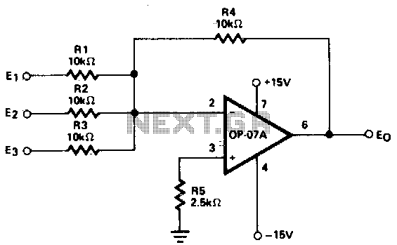
This circuit generates continuous outputs that depend on multiple input variables. The circuit in question typically employs a combination of operational amplifiers (op-amps), resistors, and potentiometers to achieve its functionality. The outputs can be tailored based on the variations...

A thorough examination of the Kapanadze video reveals that the vertical coil is wound with copper tape, forming a capacitor that captures environmental particles with the assistance of high voltage. Experiments indicate that it charges easily with minimal power...
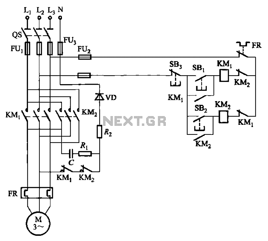
The circuit depicted in Figure 3-146 eliminates the need for a step-down transformer by utilizing the principle of energy storage through capacitor discharge for braking. It can be employed to frequently start and stop a motor with a power...
A simple two-transistor inverter circuit has been constructed for this experiment. The transformer depicted is the inverter transformer. The output voltage from the inverter is in the form of pulses, with an estimated peak value of approximately 700V. When...