
Relay Fuse For Power Supplies Circuit

The described circuit employs a relay to provide overload protection for a power supply system, ensuring safe operation under fault conditions. The relay acts as a switching device that disconnects the load from the power supply when an overload condition is detected. This is crucial for preventing damage to both the power supply and the connected components.
The circuit includes a capacitor, designated as C2, which plays a vital role in the relay reset mechanism. When an overload occurs, the relay is activated, opening the circuit and cutting off power to the load. To restore power, the relay must be reset. This is accomplished through a momentary switch that discharges the stored energy in capacitor C2. The capacitor is charged during normal operation, and when the momentary switch is pressed, it releases its stored charge, allowing the relay to return to its original state.
The design ensures that even if a short circuit persists, the system remains protected. The momentary switch provides a manual reset capability, allowing the operator to safely restore power after addressing the underlying issue. This method enhances the reliability of the power supply by incorporating both automatic protection and manual reset features, making it suitable for various applications where overload conditions may occur. A method of adding overload protection to a power supply using a relay is shown. In each circuit, the relay must be reset by a momentary switch using a charge on capacitor 02. This prevents overload if the short still exists.
Related Circuits
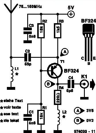
This inexpensive FM radio receiver antenna booster utilizes the BF324 TO92 style PNP transistor in a grounded-base configuration. The circuit can be employed as a... The FM radio receiver antenna booster circuit is designed to enhance the reception capabilities of...

15V active servo power supply circuit The 15V active servo power supply circuit is designed to provide a stable and regulated output voltage of 15 volts, suitable for powering servo motors and other related devices. This circuit typically employs a...
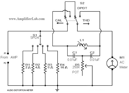
A circuit diagram of an audio distortion meter is presented here. An audio distortion meter is utilized to measure Total Harmonic Distortion (THD). The audio distortion meter is an essential tool in audio engineering, designed to quantify the level of...
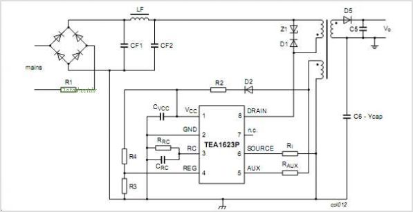
The TEA5764UK is a single-chip, electronically tuned FM stereo radio that includes a Radio Data System (RDS) and Radio Broadcast Data System (RBDS) demodulator, along with an RDS/RBDS decoder. This device is designed for portable applications and features fully...
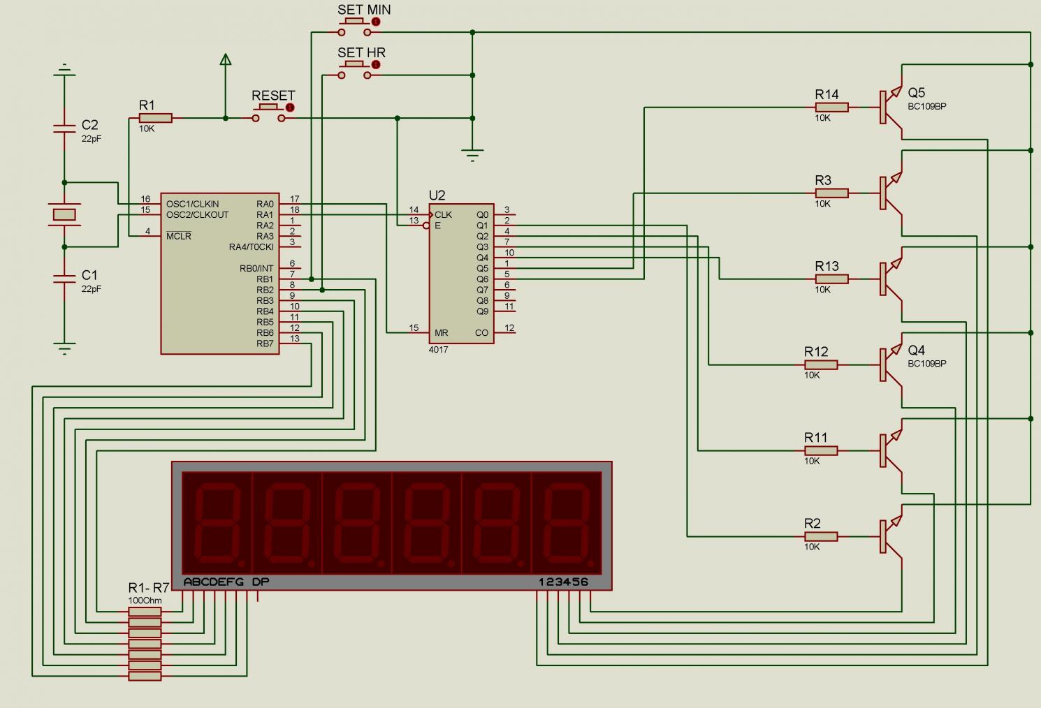
There are issues with simulating this circuit on Proteus. Please review it to ensure no errors were made. The user is also a novice. The circuit simulation in Proteus can often present challenges, especially for those who are new to...
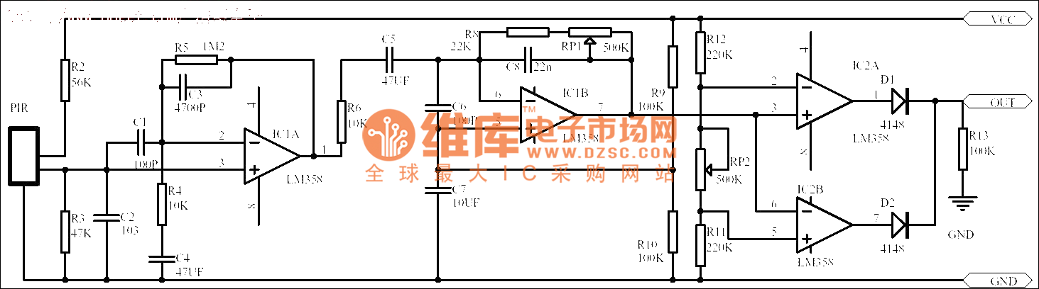
Passive human body infrared sensor circuits are generally similar in design, although some may have fewer stages. The circuit illustrated is sourced from the NICERA manufacturer and is considered a classic example. The front-end stage consists of a low-frequency...