
15V active servo power supply circuit

No description available.
Related Circuits
The circuit was taken from an old Elektor electronics magazine and is a compact design suitable for generating high-intensity lighting effects during festivals, parties, and gatherings. Diodes D1 and D2, along with capacitors C1 and C2, form a voltage...
An AC mains operated single LED flasher circuit is designed using the widely used CMOS timer chip TLC555. The entire circuit is powered directly by the grid supply of 230VAC through a capacitive potential divider and associated components. This LED...
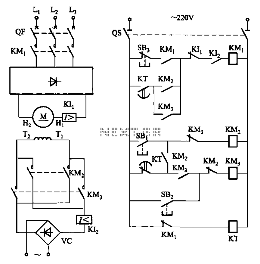
The circuit depicted in Figure 3-193 illustrates a separately excited DC motor. The brake circuit is not activated; therefore, positive reversals occur alternately using a delay action relay, ensuring that the motor reverses direction after coming to a stop. The...
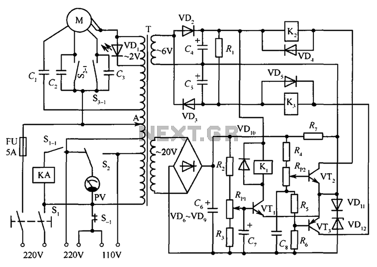
The circuit illustrated in the figure features an automatic voltage regulator (T) that utilizes a servo motor to ensure a constant output voltage. The transistors used are VT1 and VT2 (3DK9C, with a range of 65 to 85) and...
The following circuit illustrates a portable NiCd battery charger circuit diagram. The portable battery charger is designed to facilitate the charging of nickel-cadmium batteries. The portable NiCd battery charger circuit typically consists of several key components, including a transformer, rectifier,...
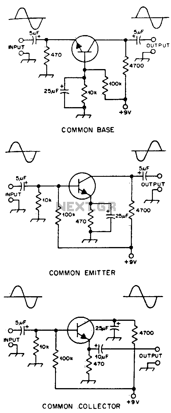
Typical component values are provided for use at audio frequencies, where these circuits are most commonly utilized. The input and output phase relationships are illustrated. The circuit design focuses on audio frequency applications, emphasizing the selection of component values that...