
Video Operated Relay

The Video Operated Relay (VOR) circuits are essential components in applications such as ATV repeater controllers and automatic videotape logging systems. These circuits are designed to detect specific video signals, primarily the horizontal sync pulses embedded within composite video signals. However, many existing designs exhibit limitations in their ability to accurately detect these signals, particularly under varying conditions of signal-to-noise ratio and differing picture content.
The LM567 phase locked loop (PLL) tone decoder is commonly utilized in these designs for sync detection. This integrated circuit is adept at detecting frequencies within a specified range, making it suitable for identifying horizontal sync signals. However, reliance solely on the LM567 can lead to suboptimal performance. The PLL's sensitivity to noise and its tuning characteristics can result in missed detections or false triggers, particularly in environments where the video signal quality is compromised.
A notable example of a less effective implementation is found in the Micro Computer Concepts VS-100 ATV Repeater Controller. This design directly couples baseband video into the LM567 without additional filtering or preprocessing. Such an approach can exacerbate the challenges of detecting horizontal sync, as the baseband video may contain a significant amount of noise that interferes with the PLL's ability to lock onto the desired sync frequency.
To enhance the performance of VOR circuits, it is advisable to incorporate additional signal conditioning stages before the PLL stage. This may include low-pass filtering to remove high-frequency noise and possibly an automatic gain control (AGC) circuit to stabilize the input signal amplitude. Furthermore, employing a more sophisticated detection method, such as a combination of analog and digital processing techniques, could improve the reliability of sync detection across a wider range of operating conditions. By addressing these factors, the performance of video-operated relays can be significantly improved, leading to more reliable operation in practical applications.Many Video Operated Relay (VOR) circuits have been published in recent years for use in connection with ATV repeater controllers or automatic videotape logging systems. Unfortunately, many of these circuits fail to properly detect certain video signals depending on their signal-to-noise ratio or their picture content.
Most designs rely on using an LM567 phase locked loop (PLL) tone decoder chip to detect the presence of horizontal sync energy in a composite video signal, and this alone is probably the greatest cause of the poor performance provided by many of these circuits. One of the worst approaches to video sync detection has been the design used by the Micro Computer Concepts VS-100 ATV Repeater Controller. This controller couples baseband video directly into an LM567 PLL tone decoder tuned to the video horizontal sync f
🔗 External reference
Related Circuits
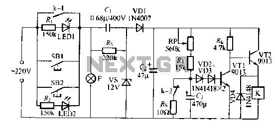
The lamp relay delay circuit is illustrated in Figure 7. Components S131 and SB2 are light buttons mounted in different locations. The lamp can operate with F. LEDs (LED1 and LED2) should be installed in SB1 and SB2 to...
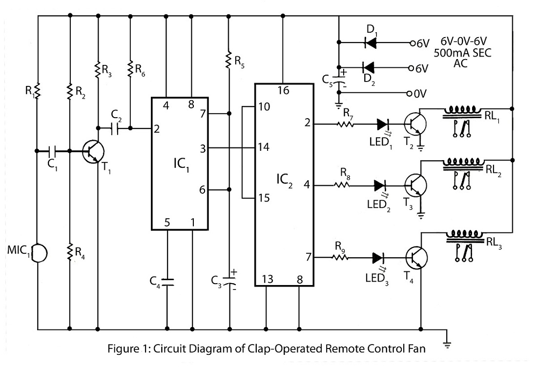
The clap-operated remote control for fans is designed to control a ten-step speed fan circuit. This includes a circuit diagram and a description of the clap-operated remote control system for fans. The clap-operated remote control system utilizes sound recognition to...
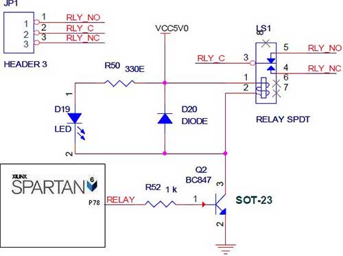
The Spartan-6 board features onboard 5V relay interfacing, as illustrated in the accompanying figure. The ULN2803 serves as a driver for the FPGA I/O lines, with the driver's outputs connected to the relay modules. A PTB connector is provided...
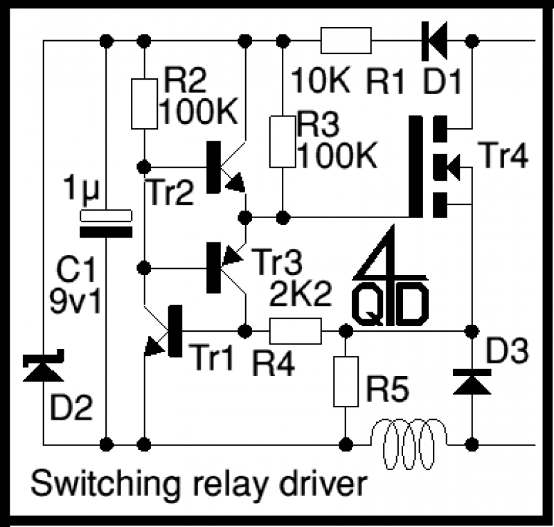
It operates by PWM (Pulse Width Modulation) - well, actually by PFM - Pulse Frequency Modulation. At power up, C1 charges up via D1 and R1. R2 will conduct, pulling the base of the emitter follower, Tr2, up and...
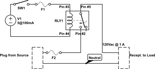
A single-pole double-throw (SPDT) switch is used to control a relay. When the relay is energized, it produces a cycling sound, which is undesirable. The goal is to have the switch operate normally in the 'on' position and return...
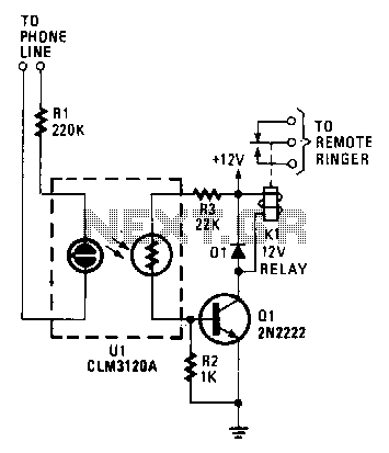
When the phone rings, the ring signal from the telephone company activates a neon lamp within a CLM3120 optocoupler. This activation results in a decrease in the resistance of the CdS cell output of the device, which in turn...