
Reliable FM transmitter

The described transmitter circuit is designed for VHF operation and incorporates a dual-stage amplification system to enhance output power significantly. The first stage utilizes the BF494 transistor, which functions as a variable-frequency oscillator, generating a signal in the VHF range. The frequency of this oscillator can be modulated using a varicap diode, allowing for frequency shifts based on audio input.
The output from the oscillator stage, approximately 50 milliwatts, is then fed into the second stage, which employs the 2N3866 transistor configured as a Class A power amplifier. This stage increases the power output by a factor of four to five, resulting in an overall transmission power of 200-250 milliwatts, suitable for short-range communication.
Coil components L1 through L4 are critical for the circuit's operation, with specific winding configurations and wire gauges specified to optimize performance. The air-core coils (L1, L2, and L3) are designed to minimize losses, while L4 utilizes a ferrite bead to function as a choke, improving stability and reducing unwanted oscillations.
The circuit's assembly is recommended on a glass epoxy board, which provides durability and insulation. An aluminum case is suggested for housing the transmitter, providing shielding against electromagnetic interference, especially for the oscillator stage. Proper thermal management is essential, particularly for the power amplifier; thus, the 2N3866 should be mounted on a heat sink to prevent overheating during prolonged operation.
Power supply considerations include the use of a 12V rechargeable battery pack consisting of ten 1.2-volt Ni-Cd cells, which ensures a stable power source for the circuit. The circuit features two potentiometers: VR1 for tuning the oscillator frequency and VR2 for controlling the output power, allowing for fine adjustments to be made for optimal transmission conditions.
It is crucial that the transmitter is not operated without a suitable antenna, as this could damage the circuit. The adjustments of the trimmers VC1 and VC2 should be performed to maximize transmission power, with VR1 set to achieve a fundamental frequency close to 100 MHz, meeting the operational requirements for effective VHF transmission.The power output of most of these circuits are very low because no power amplifier stages were incorporated. The transmitter circuit described here has an extra RF power amplifier stage, after the oscillator stage, to raise the power output to 200-250 milliwatts.
With a good matching 50-ohm ground plane antenna or multi-element Yagi antenna, this transmitter can provide reasonably good signal strength up to a distance of about 2 kilometres. The circuit built around transistor T1 (BF494) is a basic low-power variable-frequency VHF oscillator.
A varicap diode circuit is included to change the frequency of the transmitter and to provide frequency modulation by audio signals. The output of the oscillator is about 50 milliwatts. Transistor T2 (2N3866) forms a VHF-class A power amplifier. It boosts the oscillator signals power four to five times. Thus, 200-250 milliwatts of power is generated at the collector of transistor T2. For better results, assemble the circuit on a good-quality glass epoxy board and house the transmitter inside an aluminium case.
Shield the oscillator stage using an aluminium sheet. Coil winding details are given below: L1 - 4 turns of 20 SWG wire close wound over 8mm diameter plastic former. L2 - 2 turns of 24 SWG wire near top end of L1. (Note: No core (i.e. air core) is used for the above coils) L3 - 7 turns of 24 SWG wire close wound with 4mm diameter air core.
L4 - 7 turns of 24 SWG wire-wound on a ferrite bead (as choke) Potentiometer VR1 is used to vary the fundamental frequency whereas potentiometer VR2 is used as power control. For hum-free operation, operate the transmitter on a 12V rechargeable battery pack of 10 x 1.2-volt Ni-Cd cells.
Transistor T2 must be mounted on a heat sink. Do not switch on the transmitter without a matching antenna. Adjust both trimmers (VC1 and VC2) for maximum transmission power. Adjust potentiometer VR1 to set the fundamental frequency near 100 MHz. 🔗 External reference
Related Circuits
This FM transmitter circuit is compact, similar to a previous single-chip FM transmitter, but it is monophonic in nature. The circuit can be observed in the provided schematic. This monophonic FM transmitter is designed to operate on a single frequency,...
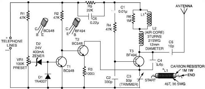
This is a straightforward telephone broadcaster transmitter designed for eavesdropping on telephone conversations. Additionally, the circuit can function as a wireless telephone amplifier. A key feature of this phone transmitter is that it draws power directly from the active...
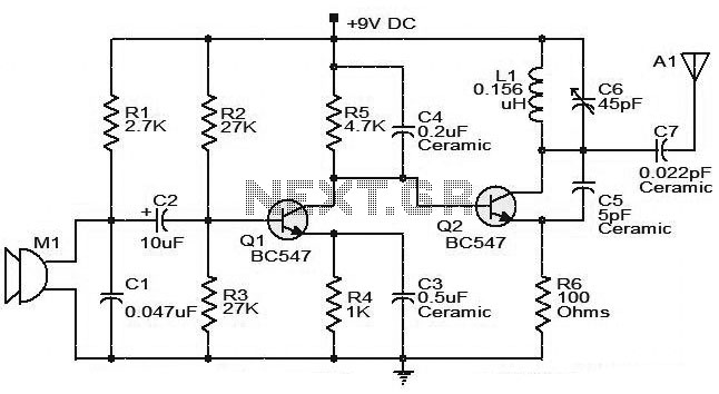
The moderate power FM transmitter circuit employs two transistors. The voice signals picked up by the microphone will be amplified by the transistor. The described FM transmitter circuit utilizes two transistors to facilitate the modulation and amplification of audio signals....

This is a design circuit diagram of a moderate power FM transmitter circuit. The circuit operates using two transistors. It consists of a complete circuit diagram. The operation of this circuit is explained as follows: the voice signals picked...
The camera is oriented to look out the side of the rocket during launch and downward during descent on the parachute. An optional external mirror can be added to enable the camera to look down during lift-off. The transmitter...
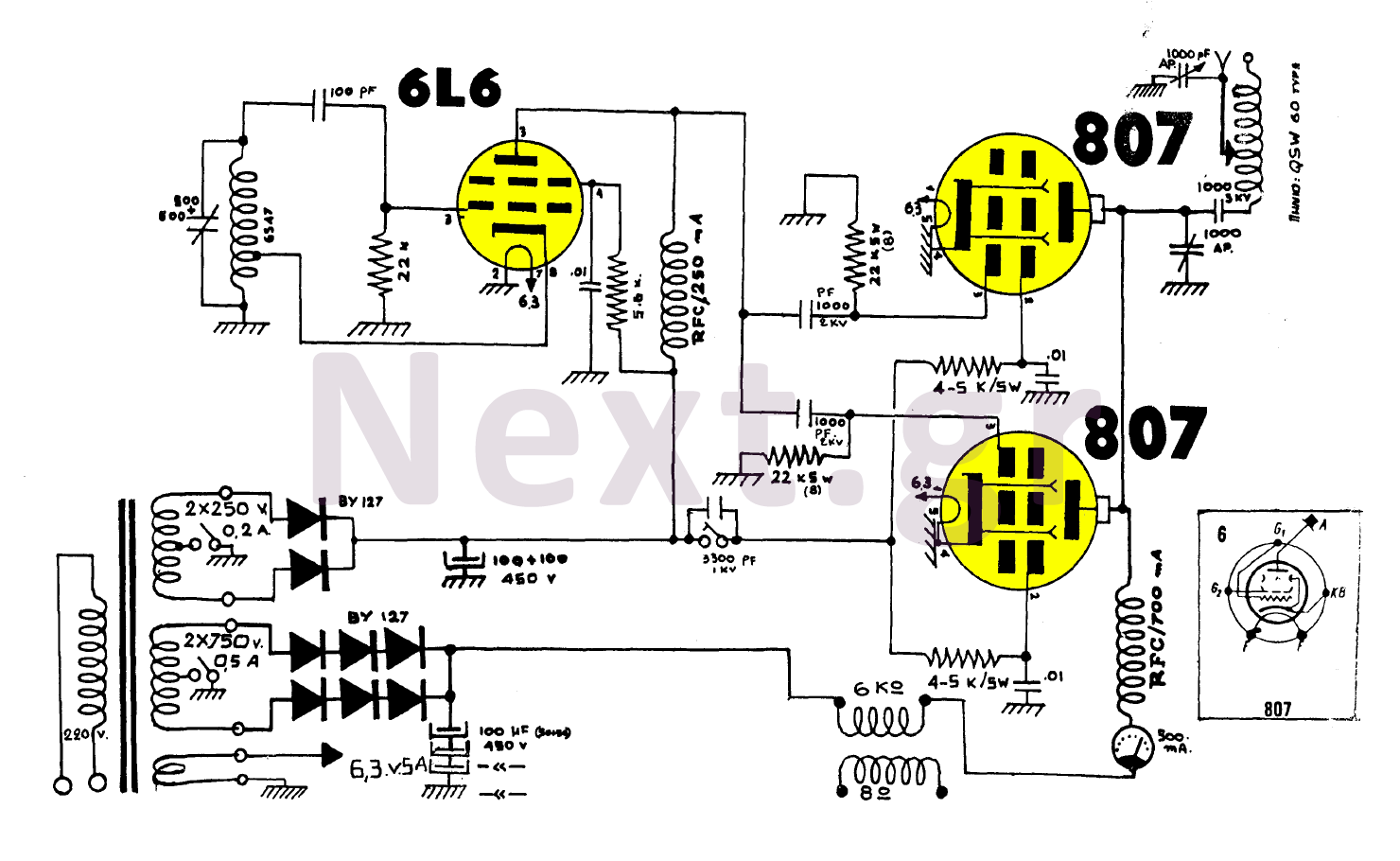
The construction utilizing two 807 tubes is robust and well-known for its performance. This design features high upward voltage and independent coupling on the output tubes, resulting in an increase in output power by several watts. While the output...