
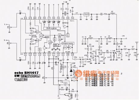
Wireless Car Alarm
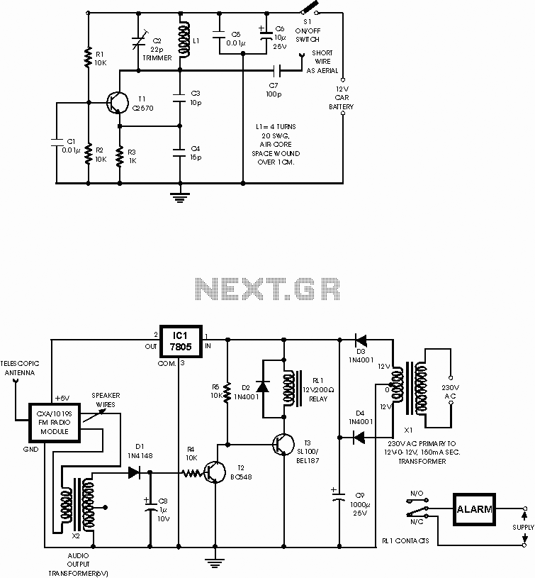
This wireless car alarm system features a dual-module architecture comprising a transmitter and a receiver, designed to enhance vehicle security through FM radio wave communication. The transmitter, integrated into the vehicle, operates on a low voltage supply within the range of 6-12V DC, making it compatible with most automotive electrical systems. For vehicles with higher voltage supplies, such as 24V, the incorporation of a voltage stabilizer is recommended to ensure safe operation of the alarm system.
The receiver module utilizes the CXA1019 IC, a compact and efficient FM radio receiver that is widely available in the market. Its tuning capability allows it to lock onto the specific frequency emitted by the transmitter, facilitating seamless communication. Under normal operating conditions, when the transmitter is active, the receiver outputs a clean signal without any interference, which prevents the conduction of transistor T2 (BC548). This condition allows the relay driver transistor T3 to remain activated, as it receives the necessary base bias via a 10k resistor (R5), keeping the relay energized and the alarm system inactive.
In the event of unauthorized vehicle movement, the disruption of the radio link triggers a change in the receiver's output, generating a hissing noise. This noise is transmitted through an audio transformer to the relay switching circuit, where it undergoes rectification and filtering through diode D1 and capacitor C8. The resulting DC voltage activates transistor T2, which in turn pulls the base of transistor T3 to ground, deactivating the relay and triggering the alarm connected to its normally closed contacts.
An important feature of this alarm system is its resilience to tampering. If an intruder disconnects the transmitter from the vehicle's battery, the receiver continues to generate hissing noise, ensuring that the alarm remains active. This design enhances the system's reliability, making it a robust solution for vehicle protection against theft. Overall, the wireless car alarm system exemplifies an effective integration of electronic components to provide a reliable and efficient security solution for vehicles.This circuit is a wireless car alarm system that is built using two circuit modules, namely modules of transmitter and receiver modules. This circuit works on FM radio waves. Car alarms can be used on vehicles that have a 6-12VDC power supp This circuit is a wireless car alarm system that is built using two circuit modules, namely modules
of transmitter and receiver modules. This circuit works on FM radio waves. Car alarms can be used on vehicles that have a 6-12VDC power supply. You can use the voltage stabilizer if your car power supply is too large (eg 24V). The mini VHF, FM transmitter is fitted in the vehicle at night when the car is parked in the car porch. The receiver unit is built with CXA1019. CXA1019 a single IC-based FM radio module which is freely available in the market, is kept inside. Receiver is tuned to the transmitter`s frequency. When the transmitter is on and the signals are being received by FM radio receiver, no hissing noise is available at the output of receiver.
Thus transistor T2 (BC548) does not conduct. This results in the relay driver transistor T3 getting its forward base bias via 10k resistor R5 and the relay gets energised. When an intruder tries to drive the car and takes it a few metres away from the car porch, the radio link between the car (transmitter) and alarm (receiver) is broken.
As a result FM radio module will generate hissing noise. Hissing AC signals are coupled to relay switching circuit via audio transformer. These AC signals are rectified and filtered by diode D1 and capacitor C8, and the resulting positive DC voltage provides a forward bias to transistor T2. Thus transistor T2 conducts, and it pulls the base of relay driver transistor T3 to ground level. The relay thus gets de-activated and the alarm connected via N/C contacts of relay is switched on. If the intruder finds out about the wireless alarm (which already turned on) and disconnects the transmitter from battery, still remote alarm remains activated.
It will not turn off the alarm because in the absence of signal, the receiver continues to produce hissing noise at its output. So the burglar alarm is fool-proof and highly reliable. 🔗 External reference
Related Circuits

This Charger Can't be used as a Power Supply, Without having a battery in place. The Battery MUST be Connected to get power out. Note: This Charger Features a Reverse polarity Indicator. Instructions: Before plugging this charger into the...
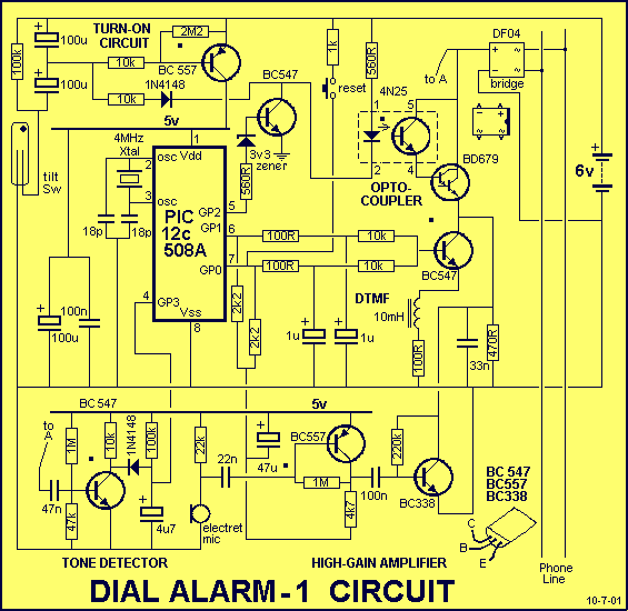
This is the lowest cost dialing alarm on the market and shows what can be done with an 8-pin microcontroller. The complete circuit is shown below. You cannot see all the features of this project by looking at the...
The circuit diagram for the receiving portion of a 2.4 GHz wireless keyboard is presented below. The 2.4 GHz wireless keyboard receiving circuit typically consists of several key components that work together to receive and process signals transmitted from the...
The following circuit illustrates a battery-powered burglar alarm sensor circuit. Features include foil tape and passive infrared sensors (PIRs), as well as magnetic reed contacts. This battery-powered burglar alarm sensor circuit is designed to provide an effective security solution for...
A basic circuit of the transistor UHF radio transmitter with a surface acoustic wave resonator (SAW) is presented. The SAW is utilized as a positive feedback element connected between the transistor's base and an LC network in parallel. In...
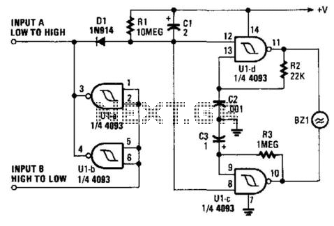
When a printer is shut down, an alarm is triggered. The input can be either a high-to-low or low-to-high transition. This corresponds to the logic level indicating whether the printer is on or off. The oscillator generates an interrupted...
Warning: include(partials/cookie-banner.php): Failed to open stream: Permission denied in /var/www/html/nextgr/view-circuit.php on line 713
Warning: include(): Failed opening 'partials/cookie-banner.php' for inclusion (include_path='.:/usr/share/php') in /var/www/html/nextgr/view-circuit.php on line 713