
remote control sckt

The miniature transmitter module operates effectively within a designated frequency range of 300 MHz, making it suitable for various remote control applications. The compact design allows for easy integration into existing systems while maintaining a lightweight profile. The use of a 9-volt PP3 battery ensures a reliable power source, facilitating operation without the need for extensive wiring or additional components.
In the relay activation circuit, the VG40R module serves as the core component, providing the necessary control signals. The relay driver transistor amplifies the signal from the VG40R output, allowing for the control of higher power loads through the relay contacts. The versatility of the system is highlighted by the ability to configure the relay for momentary activation or for preset timed operations, utilizing the IC 555 in monostable mode. The adjustable timing components enhance the system's flexibility, accommodating various application requirements.
For toggle operations, the integration of the 4017 decade counter IC allows for a straightforward method of controlling the relay state. This configuration simplifies the user interface by enabling single-button operation for both activation and deactivation of the load. The design ensures that the relay can be controlled reliably, with a brief delay introduced by the monostable multivibrator to prevent rapid toggling caused by inadvertent button presses.
To ensure optimal performance, it is crucial to implement the recommended shielding and housing practices. The use of shielded wire minimizes interference and signal degradation, while a non-metallic enclosure prevents signal attenuation, thereby maximizing the operational range of the transmitter module. Overall, this circuit design offers a robust solution for remote control applications, with a focus on user-friendly operation and reliable performance.The miniature transmitter module shown in Fig. 1, which just measures 34 mm x 29 mm x 10 mm, can be used to operate all remote control receiver-cum-switch combinations described in this project. A compact 9-volt PP3 battery can be used with the transmitter. It can transmit signals up to 15 metres without any aerial. The operating frequency of the transmitter is 300 MHz. The following circuits, using VG40R remote control receiver module measuring 45 mm x 21 mm x 13 mm, can be used to: To activate a relay momentarily (see Fig. 2), the switch on the transmitter unit is pressed, and so a positive voltage is obtained at output pin of VG40R module.
This voltage is given to bias the relay driver transistor. The relay gets activated by just pressing push-to-on micro switch on the transmitter unit. The relay remains energised as long as the switch remains pressed. When the switch is released, the relay gets deactivated. Any electrical/electronic load can be connected via N/O contacts of the relay. To activate a relay for a preset period (refer Fig. 3), the switch on the transmitter unit is pressed momentarily. The transistor gets base bias from VG40R module. As a result the transistor conducts and applies a trigger pulse to IC 555, which is wired as a monostable multivibrator. The relay remains activated till the preset time is over. Time delay can be varied from a few seconds to a few minutes by adjusting timing components. To switch on and switch off a load (refer Fig. 4), a 555 IC and a decade counter 4017 IC are used. Here the 4017 IC is wired as a flip-flop for toggle action. This is achieved by connecting Q2 output to reset terminal while Q1 output is unused. Q0 output is used for energising the relay. The relay is activated and deactivated by pressing the transmitter switch alternately. So, to activate the load, just press the transmitter switch once, momentarily. The relay will remain activated. To switch off the relay, press the transmitter switch again. This process can be repeated. Time delay of monostable multivibrator is set for about one second. Note: Short length of shielded wire should be used between VG40R receiver module output and the rest of the circuit.
The transmitter with 9V battery must be housed inside a nonmetallic (say, plastic) cabinet for maximum range of operation. Disclaimer: All the information present on this site are for personal use only. No commercial use is permitted without the prior permission from authors of this website. All content on this site is provided as is and without any guarantee on any kind, implied or otherwise.
We cannot be held responsible for any errors, omissions, or damages arising out of use of information available on this web site. The content in this site may contain COPYRIGHTED information and should not be reproduced in any way without prior permission from the authors.
🔗 External reference
Related Circuits
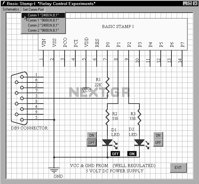
This project shows you how to build a relay controller using the Basic Stamp I interfaced to the PC serial port. The Visual Basic 5 software developed for the interface lets you interact with the Basic Stamp to turn...

The term VCXO refers to a Voltage Controlled Crystal Oscillator. The frequency of this oscillator can be fine-tuned by varying the control voltage. VCXO clock generators are utilized in a range of applications, including digital telecommunications. VCXO circuits are essential...
A phase control circuit can be utilized to regulate the power supplied to an AC load. This circuit modulates the AC waveform by cutting portions of the cycle. A phase control circuit is an essential component in various applications where...
This document outlines the process of transmitting data between a PC and an AVR Atmega8 microcontroller using the USART module. The communication utilizes the COM port of the PC, which is based on the RS232 protocol, and the UART...
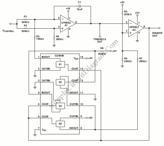
This is a schematic diagram of a micropower voltage-controlled oscillator circuit. This circuit can generate square and triangle wave outputs and only requires minimal power. The micropower voltage-controlled oscillator (VCO) circuit is designed to produce both square and triangle waveforms,...
The following circuit illustrates the AD8531 integrated circuit used for the automatic control of LCD panel backlighting. Features include the ability to compensate for aging effects and other functionalities. The AD8531 is a precision operational amplifier known for its low...