
REMOTE CONTROL ANALYZER

The schematic for the remote analyzer is designed to provide a clear and efficient method for analyzing infrared signals. The power supply section is critical, utilizing a 12.6-V AC transformer, which is rectified and filtered to provide a stable 5-V DC output. The bridge rectifier configuration, consisting of diodes D1 to D4, ensures that both halves of the AC waveform are utilized, resulting in a more efficient power conversion. Capacitor C1 smooths out the rectified voltage, reducing ripple and providing a steady input to the 7805 voltage regulator (U1).
The 7805 regulator is a popular choice for providing a reliable 5 V output, capable of supplying up to 1 A of current, which is sufficient for powering the GPIU52X infrared detector module. The inclusion of LED1 as a power indicator enhances usability by providing visual feedback that the circuit is functioning.
The GPIU52X infrared detector module (MOD1) is specifically designed to demodulate signals at a frequency of 40 kHz, which is the standard for many infrared remote control devices. This feature allows the analyzer to capture and process signals from a wide range of remote controls, making it a versatile tool for testing and troubleshooting.
The logic pulses generated by the demodulation process are routed to an oscilloscope through PL2, which is a BNC connector. This connection allows for easy monitoring and analysis of the infrared signals, facilitating detailed examination of the signal characteristics, such as pulse width and frequency, which are essential for understanding the operation of remote control systems.
Overall, the schematic diagram for the remote analyzer integrates essential components to create a functional and effective tool for infrared signal analysis, making it a valuable asset for engineers and technicians working with remote control technologies.A schematic diagram for the remote analyzer is shown. The circuit is powered from a simple 5-V supply, consisting of PL1, 51, T1, abridge rectifier (comprised of Dl through D4), capacitor C1, and a common 5-V regulator, UI. Switch 51 is the on/off control and is optional. The power-supply trans-former used in the prototype is a 12. 6-Vac unit, but any transformer that can supply at least 5. 6-Vac will do. The 12. 6-V unit was used solely because of its availability. The output of T1 is full-wave rectified by diodes Dl through D4 and filtered by C1. The bumpy dc output from the capacitor is regulated down to 5 V by UI, a 7805 integrated regulator, LED1 acts as a power indicator to let you know that the circuit is active. The 5-Vdc powers a GPIU52X infrared-detector module* (MODl), which demodulates the 40-kHz carrier used by most infrared remotes.
After demodulation, the resulting logic pulses are sent to an oscilloscope via PL2, a BNC connector. 🔗 External reference
Related Circuits
Many audio systems consist of separate units, and due to economic reasons, only the amplifier is equipped with a remote control receiver module. Control signals are then transmitted to other units using patch cables. For instance, the tuner and...
A relay-based on/off controller on the other hand can be very efficient. A typical relay has a contact resistance of 3 milliOhm. At 20A, this translates to a voltage drop of 0.06 volts, with a power loss of 1.2W....
The microcontroller used is 0822 zilog encore! 8k series (soic,28pin) as shown on the figure. Is a programmable microcontroller, the functions used are the GPIO and the UART of the chip. GPIO is used on led indicators, and the...
The prototype for this model is one of a DSG class of 24 locomotives built in 1981 by Toshiba for the New Zealand Railways. These locomotives weigh 56 tonnes and have two diesel engines, providing a total of 750...
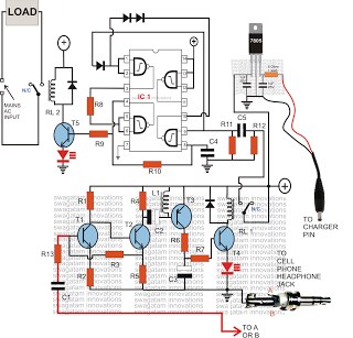
Control any electrical device from anywhere in the world using a cell phone, without incurring costs for individual commands. This system allows operation of various appliances, such as vehicles, doors, and air conditioners, with a simple button press on...
Turning electrical devices ON or OFF using a remote control is a well-established concept, with numerous devices available that perform this function effectively. To create such a device, it is necessary to construct a receiver and a transmitter, as...