
R/C On/Off Motor Controller with Brake

A relay-based on/off controller is a straightforward circuit design that allows for the control of high current loads, such as electric motors, using low power control signals. The relay serves as an electromechanical switch, providing isolation between the control circuit and the load circuit.
In this configuration, the relay's contact resistance is a critical parameter; with a typical value of 3 milliOhms, it results in a minimal voltage drop of 0.06 volts when a current of 20A flows through it. This low resistance ensures that the relay operates efficiently, minimizing energy loss in the form of heat. The power loss across the relay contacts can be calculated using the formula P = I²R, which yields a power loss of 1.2W at the specified current. Additionally, the relay coil itself consumes approximately 0.4W, which is essential to consider in the overall power budget of the system.
In applications where motor control is needed, a double throw relay can be advantageous. This configuration allows for the implementation of a braking mechanism; when the relay is switched to its alternate position, the motor can be effectively shorted, providing dynamic braking and enhancing the control of the motor's stopping characteristics.
However, it is important to note the limitations of a relay-based controller. The primary drawback is the lack of speed control; the motor can either be fully energized or completely deactivated, which may not be suitable for applications requiring variable speed operation. Therefore, while this type of controller is efficient for specific uses, such as in electric gliders, where the simplicity and reliability of on/off control is beneficial, it may not meet the requirements of more complex motor control applications.A relay-based on/off controller on the other hand can be very efficient. A typical relay has a contact resistance of 3 milliOhm. At 20A, this translates to a voltage drop of 0.06 volts, with a power loss of 1.2W. The relay itself typically consumes around 0.4W. And, by using a double throw relay, one gets a brake for free. There are two main problems with a relay-based on/off controller. One is that there is no control over motor speed; it`s either off or it`s at full throttle. Such a controller is best suited to electric gliders, which for their size, typically h 🔗 External reference
Related Circuits
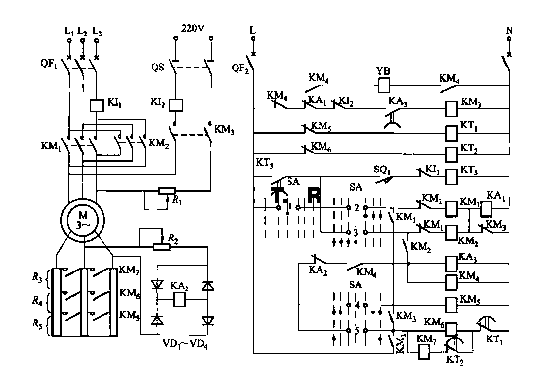
Figure 3173 illustrates a control circuit for a wound rotor induction motor that enables mechanical braking, dynamic braking, and reverse braking functions. The circuit includes various components such as relays, contactors, and time relays to manage the motor's speed...
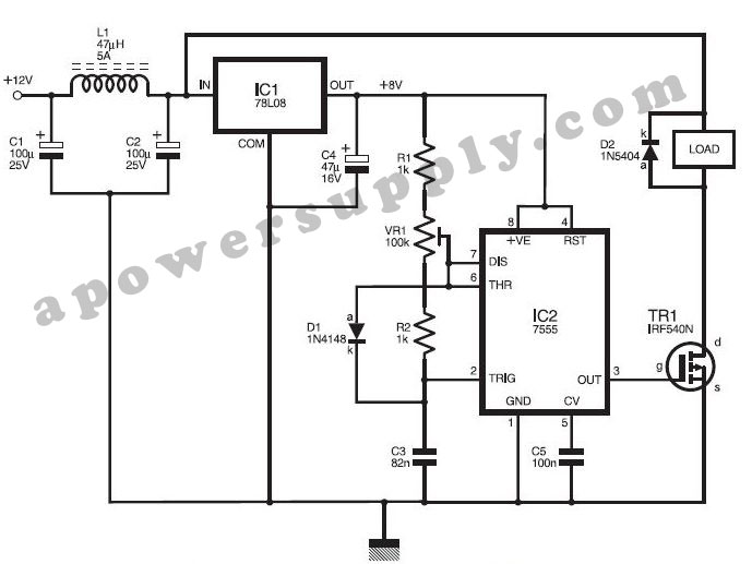
This DC power supply controller is regulated by pulse width modulation (PWM), which is generated by a circuit utilizing timer IC2 7555 according to a specific duty cycle formula. The described DC power supply controller employs a timer IC, specifically...
A stepper motor is an effective solution for achieving high-precision motion control. To operate a stepper motor, a corresponding control circuit is required. A stepper motor control circuit typically consists of several key components that facilitate the precise movement of...
Car and Motorcycle Battery Tester Circuit. Going camping today often requires bringing various electronic devices for daily activities or entertainment. Typically, a charged lead-acid battery and a power source are essential. The Car and Motorcycle Battery Tester Circuit is designed...
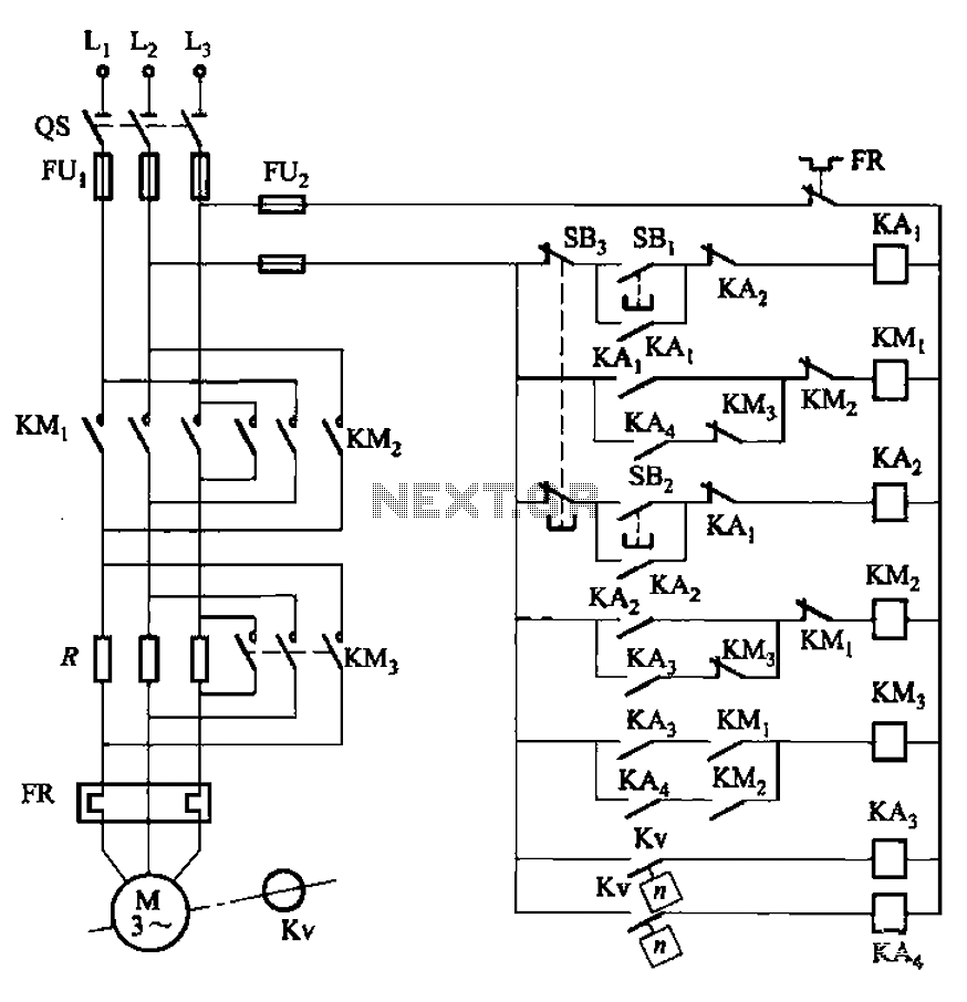
The circuit illustrated in Figure 3-130 differs from the circuit in Figure 3-129 in that when the stop button SB3 is pressed, the electric motor initiates braking. Furthermore, during both the startup and braking phases, the motor power lines...
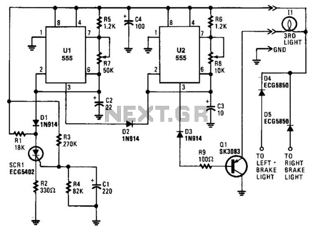
When power is first applied, three events occur: the light-driving transistor (Q1) is activated due to a low output from U2 at pin 3; timer U1 begins its timing cycle, with the output at pin 3 going high, which...