
remote control and Intruder detector

The described ultrasonic transmitter circuit operates on principles established in the mid-1970s, utilizing discrete components rather than integrated circuits (ICs). The circuit's primary function is to generate ultrasonic signals that can be used for remote control applications, typically in conjunction with a corresponding receiver circuit.
The transmitter circuit likely comprises a signal generator, which could be a simple astable multivibrator configuration using bipolar junction transistors (BJTs) or field-effect transistors (FETs) to produce a square wave signal. This square wave is then fed into a piezoelectric transducer, which converts the electrical signal into ultrasonic sound waves. The frequency of the generated signal is critical and is typically in the range of 20 kHz to 40 kHz, which is beyond the audible range for humans.
To enhance the performance and efficiency of the circuit, operational amplifiers (op-amps) could be integrated into the design. Op-amps can be utilized to amplify the output signal from the signal generator before it reaches the transducer, ensuring that the ultrasonic waves produced are strong enough to be effectively transmitted over the desired distance. Additionally, op-amps can be employed in filtering applications to eliminate any unwanted noise from the signal, thereby improving clarity and reliability.
The circuit is designed for single-channel operation, which limits its functionality compared to modern multi-channel systems. In the past, multi-channel ultrasonic chips were available, allowing for more complex communication setups. However, as ultrasonic technology has become less prevalent in commercial applications, many of these components are now considered obsolete, making the design of new systems more challenging.
In summary, the ultrasonic transmitter circuit described employs fundamental electronic principles and discrete components to generate ultrasonic signals for remote control applications. Its design can be enhanced with the inclusion of op-amps to improve signal strength and reduce noise, although its single-channel limitation reflects the technological constraints of its era.These ultrasonic circuits are all quite old: my notes date them at mid-70s so they don`t use ICs. Nevertheless there are several places where an op-amp would possibly simplify things. Despite their age I hope they are of interest: certainly basic principles don`t change. This transmitter is designed to work with the next circuit as a remote control transmitter/receiver. It is only a single channel and you could once get multi-channel chips for the whole job. However ultrasonics have fallen out of favour commercially so I think most of these chips are now obsolete. 🔗 External reference
Related Circuits
A relatively simple circuit for controlling a stair walkway light with a delay feature. The circuit has a drawback in that the voice activation is somewhat less sensitive, making it sometimes difficult to trigger with general conversation. However, it...
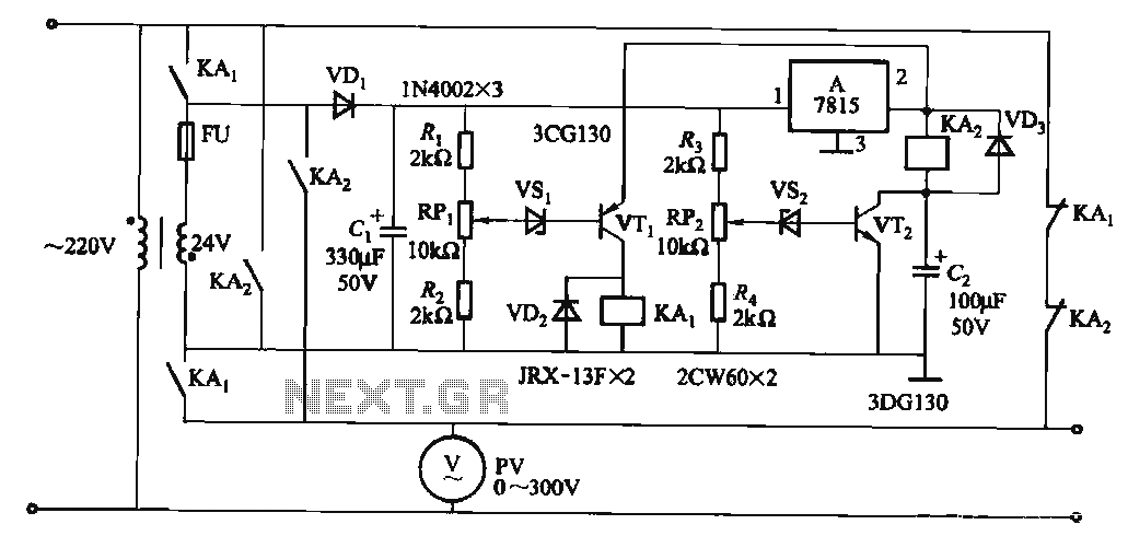
When the input voltage is in the range of 170-260V AC, the output AC voltage falls between 187-231V. The transformer ratio is k = 24/220 = 0.11. If the input voltage drops below 170V, relay KAi activates (adjusted by...
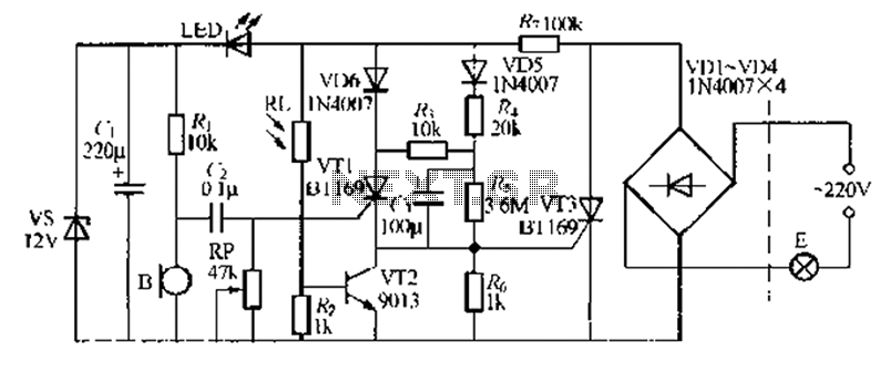
It is easy to miss the sound of a doorbell while watching TV. This circuit addresses the issue by providing a visual indication, such as a lamp or an LED. Connecting a lamp directly in parallel with the doorbell...
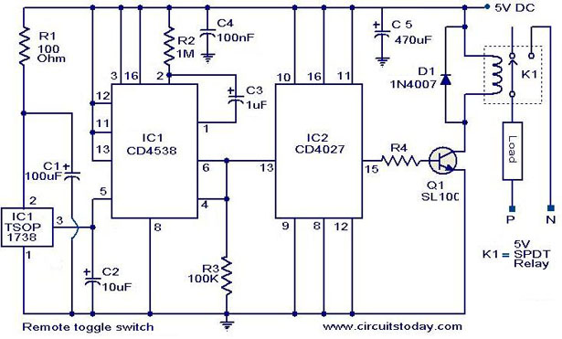
At the application level, this circuit is similar to the previously mentioned circuit, with the primary distinction being the method of implementation. This circuit is designed to toggle any electrical appliance between ON and OFF states using a TV...
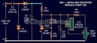
This document presents an infrared remote control tester circuit that can be constructed at a low cost. The circuit is built around the infrared receiver module TSOP1738. The state of the remote control can be observed through the sound...

This project focuses on the design and development of a theft control system for automobiles, aimed at preventing and controlling vehicle theft. The system utilizes an embedded design based on GSM and GPS technology. It is installed within the...