
remote_control circuit

The described circuit utilizes a photocell as the primary sensing element, which is sensitive to light levels. The photocell's resistance decreases with increasing light intensity, allowing for the creation of a voltage divider when combined with resistive components. This voltage divider's output voltage is directly proportional to the light intensity, which can be monitored and amplified using an operational amplifier or a transistor-based circuit.
To implement this design, the circuit can include a power supply, typically a DC voltage source, connected to the photocell and resistive components. The output from the voltage divider can be fed into a comparator circuit to determine when the voltage exceeds a certain threshold, indicating that the light level is sufficient to trigger the desired action. This comparator can be configured with hysteresis to prevent rapid switching due to minor fluctuations in light levels.
The activation of the relay or SCR can be accomplished by connecting the output of the comparator to the gate of the SCR or the coil of the relay. This allows the circuit to control higher current loads, such as lights or motors, which require more power than the photocell can handle directly.
The placement of the photocell in a matte black tube is crucial to ensure that it only responds to the intended light source, thereby preventing false triggers from ambient light. The potentiometer R2 allows for fine-tuning of the sensitivity of the photocell, enabling the user to set the threshold level at which the circuit will activate based on their specific requirements.
Overall, this circuit design offers versatility in its applications, allowing users to creatively implement it in various scenarios, from simple lighting controls to more complex automation systems.At this circuit you can give a variety of utilities, from an alarm, to open a door, turn on a light in the garden or courtyard, and so on. Your imagination has the last word. HOW IT WORKS: The operating principle is based on the properties of a photoelectric PHOTOCELL or light, the substances with which this is constructed, its resistance varies w
ith the degree of light it receives. When this component is placed in series with other components resistive, and then connect to the poles of a power supply, you get a voltage divider, which is dependent on the light. When these variations amplified voltage properly, we can activate a relay (relay, relay, circuit breaker), an SCR (silicon controlled rectifier), a triac, and so on.
and I manage teams with higher amperage. The PHOTOCELL (light) should be placed inside a tube in black matte color so they do not receive the light of day or other than that which will operate the circuit. The potentiometer R2 is responsible for adjusting the amount of voltage that should receive the PHOTOCELL and thus with that degree of light should turn on the circuit.
🔗 External reference
Related Circuits
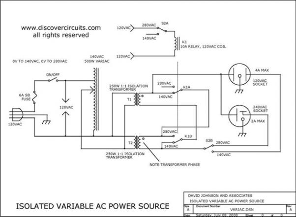
Variable AC Power Supply Circuit. In electronics, it is often useful to have a fully isolated variable AC power supply. With such a device, one can safely test various AC-powered circuits. A variable AC power supply circuit is an essential...
Replacing the LC modulation circuit with an active filter allows for the elimination of large and costly inductance coils in frequency shift key control demodulators. This approach not only reduces the size of the circuit but also enhances the...
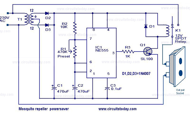
The circuit diagram of a mosquito repellent power saver circuit is provided along with a detailed explanation. The mosquito repellent power saver circuit is designed to efficiently operate a mosquito repellent device while minimizing energy consumption. This circuit typically integrates...
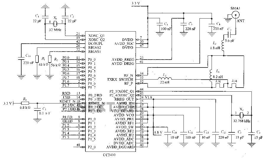
Figure C1 and C2 depict a 22 pF capacitor connected to a 32 MHz crystal oscillator circuit, which utilizes a quartz crystal for standard operation. Capacitors C3 and C4, each rated at 15 pF, are connected to a 32.768...
Individuals seeking a distinctive gift for Christmas and New Year may find this project appealing. Certification of this project will undoubtedly create a preference for it. The project in question appears to be a creative endeavor aimed at providing a...
This is a birthday heart circuit. No much description is available but you can use your experienced imagination! The birthday heart circuit is designed to create a visually appealing display, often used as a decorative element for celebrations. The circuit...