
Universal Triac Control with Optocoupler

The universal triac controller circuit is designed to enhance the performance of triacs, particularly in low-temperature environments where standard operation may be compromised. The circuit employs an optocoupler to provide electrical isolation between the control side and the load side, ensuring safe operation and protecting sensitive components from high voltage spikes.
The configuration typically includes a triac, an optocoupler, resistors, and capacitors. The optocoupler is used to control the gate of the triac, allowing for low-voltage control signals to manage higher voltage loads. This is particularly advantageous in applications where the control circuit operates at a lower voltage, such as microcontrollers or digital logic circuits.
In the circuit, the optocoupler's LED is driven by the control signal, which activates the phototransistor on the output side. When the phototransistor conducts, it triggers the gate of the triac, allowing current to flow through the load. The use of a resistor in series with the LED ensures that the optocoupler operates within its specified current limits, while additional components may be employed to filter noise and stabilize the circuit.
For optimal performance, it is crucial to select a triac that matches the load specifications, including voltage and current ratings, and to ensure that the optocoupler is capable of providing sufficient gate current to trigger the triac reliably. This configuration not only improves the reliability of the triac operation in low-temperature conditions but also enhances overall circuit safety and efficiency.This universal triac controller circuit with optocoupler solves the problem that triacs have when functioning at low temperatures (triac needs higher gate. 🔗 External reference
Related Circuits
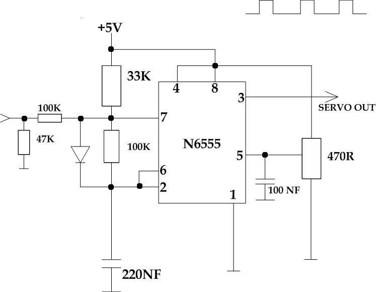
This circuit takes a standard 0-10V control voltage (for example, from an analog light control desk) and outputs a standard 1-2 ms control pulse for RC servo motors. The components used in this circuit include: - 2 x 100...
Many consumer electronic devices, such as televisions, VCRs, and CD/DVD players, utilize infrared remote controls. In certain situations, it is beneficial to enhance the control range. This circuit is designed to receive the infrared signal from a remote control...
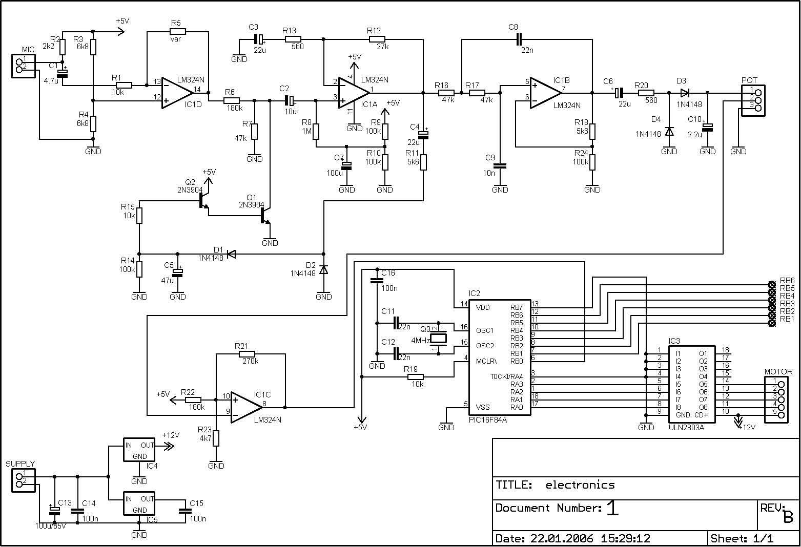
The PIC microcontroller is capable of controlling a motor after each beat, with the option to bypass certain beats using pushbuttons. The rotation speed and duration can also be adjusted within specified limits to prevent register overflow or underflow....
A two-phase servo motor features a field winding and a control winding. When there is a 90° phase difference between the two, it generates rotational torque. A potentiometer connected to the motor shaft measures the voltage difference between the...
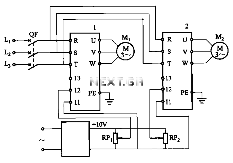
Adjust the potentiometers RPi and RPz to modify the speed of two motors. The circuit utilizes two potentiometers, designated as RPi and RPz, to control the speed of two separate motors. Each potentiometer is connected in a voltage divider configuration,...
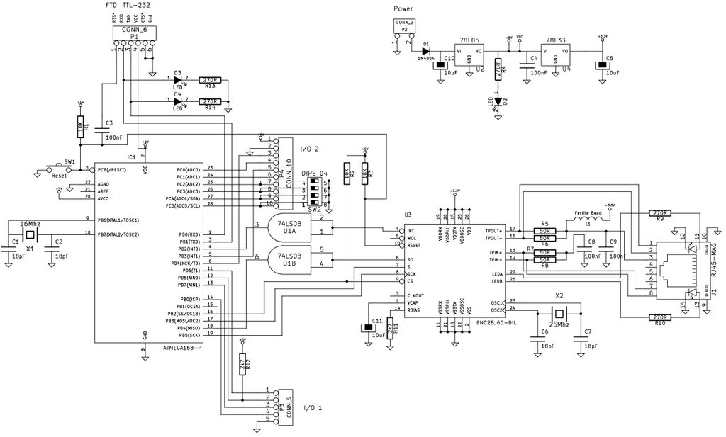
The Arduino is a simple and accessible controller platform suitable for various projects. A few months ago, an Ethernet shield was purchased for it. The Arduino platform is widely recognized for its user-friendly interface and versatility, making it a popular...