
Remote Control Tester

The following diagram illustrates the circuit schematic for a 12V stereo tone control, which is also available as a kit at local electronic parts stores. The circuit is based on a standard tone control design, utilizing two FCS9014 transistors in each channel, totaling four transistors for the 12V configuration. Additionally, a low resistance connection tester can be employed as a cable or wire tester, suitable for soldered joints and other types of connections with resistance values between 0.25 and 4 ohms. This simple circuit uses a 741 op-amp in differential mode as a continuity tester, measuring the voltage difference between the non-inverting and inverting inputs.
Furthermore, the following diagram represents the schematic for an Active Tone Control circuit, commonly referred to as "ACTOR." The Active Tone Control circuit enhances the loudness of audio signals (bass and treble) using the Baxandall system. This circuit does not require a dedicated power supply.
Lastly, there is a description of a wireless car alarm system constructed using two circuit modules: a transmitter module and a receiver module. This system operates on FM radio waves and is compatible with vehicles that have a 6-12V DC power supply. A voltage stabilizer can be employed if the car's power supply exceeds this range.Remote control tester circuit diagram. The tester is designed around infrared receiver module TSOP1738. Operation of the remote control is identified by a tone from the buzzer. The circuit is sensitive and has a range of about 5 metres. The integrated IR receiver detects, amplifies and demodulates IR signals from the remote control unit. The piezo buzzer connected at its output sounds to tell us the existence of transmission from the remote control unit. Here is the remote control tester circuit. This circuit is really a simple and easy tester for verifying the basic operations of an infrared remote control unit.
It is low-cost and very easy to construct. The tester is designed around infrared receiver module TSOP1738. Operation of the remote control is identified by a tone from. The circuit, consisting of an infrared transmitter-receiver pair, utilizes IR beam transmission to switch the toy car on` or off`, yeah. it will be only switching on and switching off, you may modify this circuit to make the toy car to turn left or right.
To operate the toy car, you have to hold the. The following diagram is the circuit diagram of 12V stereo tone control which also available in kit, you may find the kit at electronic part store around your place. The circuit build based on ordinary tone control circuit, using 2 transistors FCS9014 in each channel, so there are will be 4 transistors in this 12v.
Here the low resistance connection tester which can be used as cable or wire tester, soldered joints and other types of connection with resistance value between 0. 25 and 4 ohm. Notes This simple circuit uses a 741 op-amp in differential mode as a continuity tester. The voltage difference between the non-inverting and inverting inputs is. The following diagram is the schematic diagram of Active Tone Control circuit, or we often call thic circuit as "ACTOR" Active Tone Control or ACTOR is a electronic audio circuit that serves to increase the Loudness (Bass and Treble audio signal) is active because it uses the Baxandall system.
This circuit does not use a. This circuit is a wireless car alarm system that is built using two circuit modules, namely modules of transmitter and receiver modules. This circuit works on FM radio waves. Car alarms can be used on vehicles that have a 6-12VDC power supply. You can use the voltage stabilizer if your car power supply is too. 🔗 External reference
Related Circuits
A quartz crystal tester is required to determine the functionality of a crystal, indicating whether it is operational or defective. This tester features an LED light indicator. A quartz crystal tester is an essential tool for evaluating the condition of...
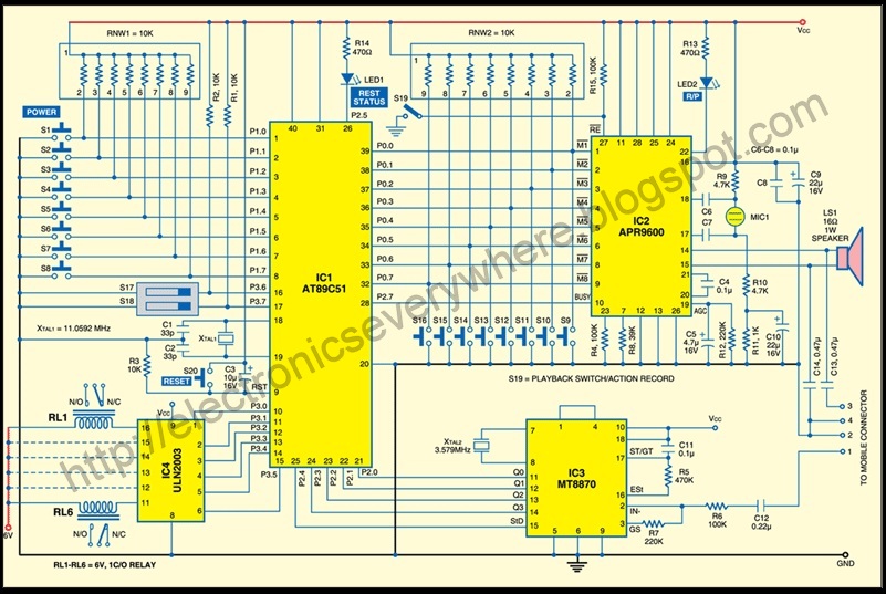
A circuit that allows for the operation of home appliances such as lights and water pumps from a remote location, such as an office. This system enables users to turn off appliances with their cellphones if they forget to...
The UBA2021 can be utilized as a 600 V lamp controller and half-bridge driver integrated circuit (IC) for high-power applications. It is designed for long-life compact fluorescent lamp (CFL) and tubular fluorescent lamp (TL) applications. The UBA2021 is a versatile...
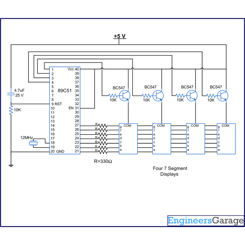
A digital clock displays time in a digital format. The circuit outlined here shows the time with double-digit minutes and two digits for seconds across four seven-segment displays. The segments of the displays are interconnected with the 8051 microcontroller...
A circuit that activates a relay upon detecting audio pulses from one channel of an MP3 player. The intention is to synchronize recorded audio pulses with music to control a motor for mouth movement. For a stereo player, music...
This circuit utilizes the widely available LM3914 integrated circuit (IC), which is straightforward to operate and does not require external voltage regulators due to its built-in voltage regulation capabilities. It can be powered from various sources. When the test...