
lm3914 ic based on simple battery tester

This circuit design effectively leverages the LM3914 IC's capabilities for voltage measurement and display. The IC is configured to provide a visual indication of the battery voltage level, which is crucial for monitoring the health of the vehicle's electrical system. The high-impedance voltage divider plays a pivotal role in scaling down the car battery voltage to a manageable level for the IC, ensuring accurate readings without loading the circuit.
The choice of a 4700µF capacitor is significant; it serves to mitigate voltage spikes and noise that could lead to inaccurate readings, especially in environments with high electromagnetic interference, such as those found in gasoline-powered vehicles. The inclusion of an offset trimmer allows for fine-tuning of the circuit, enabling it to accurately measure a wider range of voltages, which can be particularly useful for diagnosing battery issues.
The LM3914 can operate in two modes: bar graph and dot mode. By disconnecting pin 9, the circuit shifts to a dot mode, which can be more suitable for certain applications where a discrete voltage level indication is preferable. This flexibility in display options enhances the usability of the circuit for various diagnostic purposes.
Overall, this circuit is a robust solution for monitoring automotive battery voltage, providing essential feedback for vehicle maintenance and ensuring reliable operation. The design is modular and can be adapted for different applications by modifying the voltage divider network or the display configuration, making it a versatile tool for electronics enthusiasts and professionals alike.This circuit employs the popular and easy to find LM3914 IC. This kind of IC is quite very simple to drive, requires no voltage regulators (it features a built in voltage regulator) and can be powered from almost every resource. Once the test switch is pushed, the Car battery voltage is supply into a high impedance voltage divider.
His function is to divide 12V to 1, 25V (or lower values to reduced values). This solution is much better than enabling the internal voltage regulator set the 12V sample voltage to be feed into the internal voltage divider simply because it cannot regulate 12V if the voltage falls lower (linear regulators only step down). Simply wiring with no change, the regulator provides secure 1, 25V which can be fed into the precision internal resistor cascade to create sample voltages to the internal comparators.
In any case the default establishing let you to determine voltages between 8 and 12V however you can measure even from 0V to 12V setting the offset trimmer to 0 (but i believe that below 9 volt your vehicle would not start). There is a smoothing capacitor (4700uF 16V) it is used to adsorb EMF noises produced from the ignition coil if you`re testing the battery during the engine working.
Diesel engines would not need it, but i am not sure. If you want more a level graph rather than a bar graph simply disconnect pin 9 on the IC (MODE) from power. The calculations are usually simple (default). 🔗 External reference
Related Circuits
While conducting background research on the Philips I2C bus, an application note authored by Herman Schutte from Philips Semiconductors Systems Laboratory in Eindhoven was discovered. Mr. Schutte detailed an efficient method for interfacing sections of the I2C bus operating...

If the total circuit resistance can be significantly reduced to less than 0.1 Ohm and a load of 0.4 Ohm or less is connected, over 1 kilowatt of free electrical energy can be obtained. There are two discrete voltage...
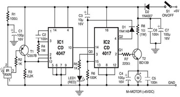
The following circuit illustrates an Infrared Toy Car Motor Controller Circuit Diagram. This circuit is based on the 4017 IC. Features: operating at .. The Infrared Toy Car Motor Controller Circuit utilizes a 4017 Decade Counter IC, which is integral...
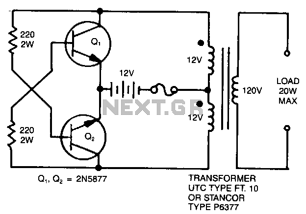
A simple 120 V to 24 V center-tapped control transformer, along with four additional components, can accomplish the task. This circuit produces a clean 200 V peak-to-peak square wave at 60 Hz and is capable of supplying up to...
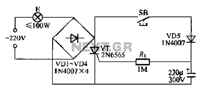
This circuit is a simple connection delay lamp circuit. When the lights are turned on and the switch is pressed, the power supply is activated. The capacitor charges rapidly, causing the thyristor (VT) to open, which in turn lights...

This circuit was designed to control power delivery to a Peltier cooler in a vehicle. The power to the load from the vehicle's battery is managed by a Single Pole Double Throw (SPDT) relay. The circuit utilizes an SPDT relay...