
DC 12V Battery Charger Circuit Schematic

The DC 12V battery charger circuit is designed to efficiently charge gelled electrolyte lead-acid batteries, which are commonly used in various applications due to their reliability and performance characteristics. The circuit typically consists of several key components: a transformer, a rectifier, a filter capacitor, a voltage regulator, and various protection elements such as diodes and fuses.
The transformer steps down the AC mains voltage to a lower AC voltage suitable for charging the battery. The rectifier, often implemented with diodes, converts the AC voltage to pulsating DC. The filter capacitor smooths the output from the rectifier, providing a more stable DC voltage to the battery.
A voltage regulator may be included to ensure that the output voltage remains constant and within safe limits for the battery being charged. This is critical to prevent overcharging, which can damage the battery and reduce its lifespan. Protection components, such as fuses, are incorporated to safeguard the circuit against overcurrent conditions, while diodes can be used to prevent reverse current flow from the battery back into the charger.
The design may also incorporate a charging indicator, such as an LED, to visually indicate the status of the charging process. Overall, this circuit provides a reliable and efficient solution for charging gelled electrolyte lead-acid batteries, ensuring optimal performance and longevity.DC 12V Battery Charger Circuit Diagram. This circuit is a high performance charger for gelled electrolyte lead-acid batteries.. 🔗 External reference
Related Circuits
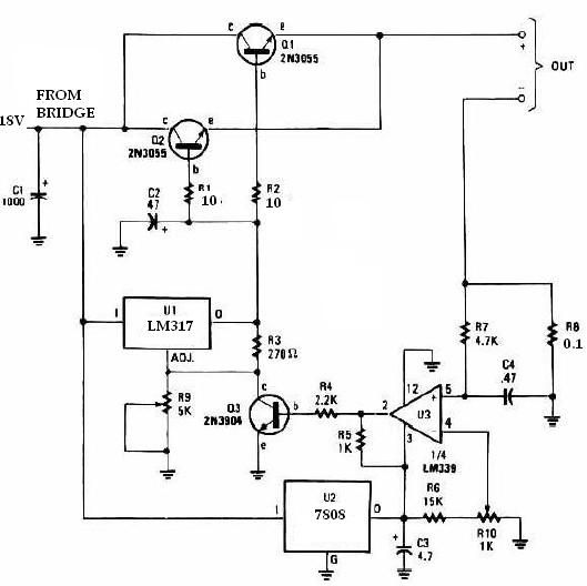
This universal battery charger utilizes the LM317 voltage regulator and features an adjustable output voltage along with a constant-current charging circuit, making it suitable for charging most NiCad batteries and various other battery types. The LM317 universal battery charger...
Even if the circuit is simple, it complies with all conditions regarding distortion and frequency response. The input resistance is 250K ohms, and it can drive loads ranging from 100 ohms to 2K ohms. The described circuit is a fundamental...
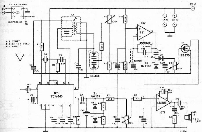
A simple FM CB radio receiver can be constructed using the electronic diagram provided. This FM CB radio receiver circuit utilizes a TCA440 integrated circuit and operates at an intermediate frequency of 455 kHz. The input filter is a...
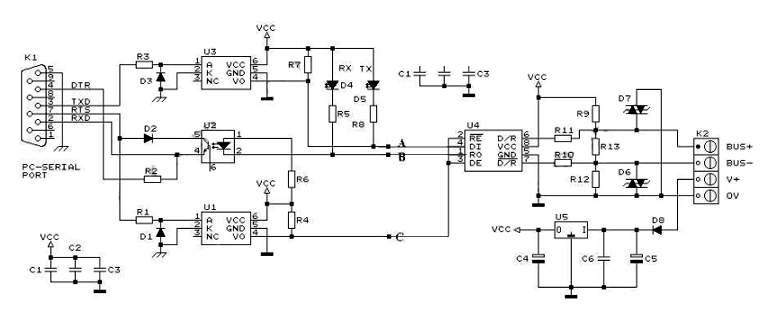
RS232 to RS485 Converter Circuit Schematic. RS232 to RS485 converters are primarily utilized in industrial and commercial settings. The RS232 to RS485 converter circuit is designed to facilitate communication between devices using different serial communication standards. RS232 is commonly found...
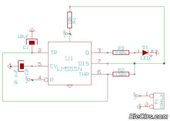
This is a very simple 555 timer circuit that serves as a straightforward theft deterrent, which may be just as effective. The idea is to have a flashing red LED indicate that your car is protected. This device can...
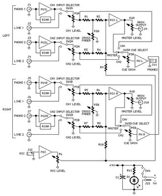
The mixer circuit features two line inputs and two microphone inputs, along with two line outputs. The microphone inputs are designed for low-impedance dynamic microphones with an impedance range of 200-1000 ohms. This simple mixer was specifically designed to...