
REMOTE CONTROL TRANSMIITER

The described FM transmitter circuit operates within the standard FM broadcast frequency range, facilitating the transmission of audio signals encoded in frequency modulation. The 19 kHz tone is particularly significant as it serves as a pilot tone, allowing FM receivers to detect the presence of an FM multiplex signal, which is essential for stereo broadcasting.
The circuit features three inductors: L1, L2, and L3, each playing a crucial role in the transmitter's performance. L1, with its 9 turns of #26 enameled wire, forms the primary inductor in the oscillator circuit, which is coupled to a 10-kΩ carbon resistor to stabilize the oscillation frequency. The construction of L2, with its 2 turns over L1, acts as a feedback winding that enhances the frequency stability and modulation characteristics of the transmitter. L3, having 7 turns of wire on another 10-kΩ resistor, likely serves as a part of the output stage, ensuring that the signal is adequately amplified before transmission.
The use of a 15 cm wire antenna (L4) is optimal for the intended frequency range, as it allows effective radiation of the FM signal. The antenna length is chosen to be a fraction of the wavelength of the transmitted signal, ensuring efficient transmission. This design can interface with external devices, making it versatile for various applications, such as in home audio systems or for educational purposes in demonstrating FM transmission principles.
Overall, this FM transmitter circuit is designed for effective signal generation and transmission, utilizing standard components to achieve reliable performance within the specified frequency range.This transmitter sends an FM signal in the 88-to 108-MHz range, with a tone of 19 kHz. This can be used to activate the FM MPX pilot carrier indicator, which can be interfaced to external devices. L4 is for use with a 15 CM wire antenna. L1 is 9 turns of #26 enamelled wire on a 1/4-W 10-k © resistor (carbon type), L2 is 2 turns wound over L1.
L3 i s 7 turns of #26 enamelled wire on a 10-k © 1/4-W resistor. 🔗 External reference
Related Circuits
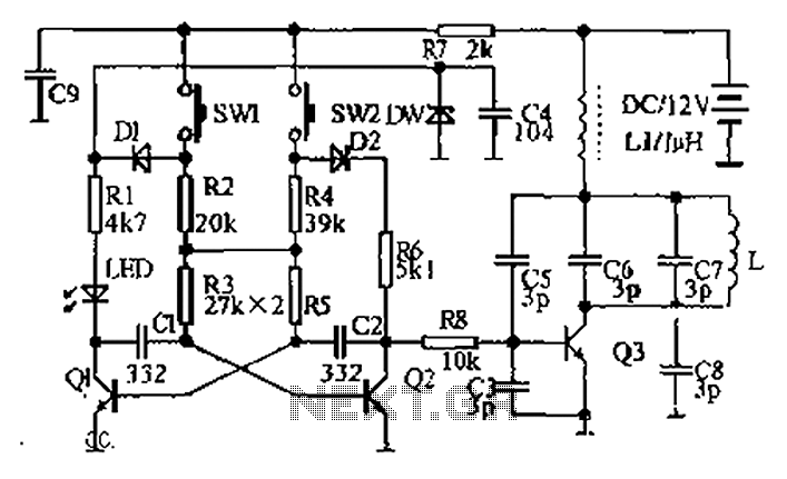
The circuit diagram illustrates a dual radio remote control switch system. The transmitter section features Q3, which generates a high-frequency carrier signal, while Q1 and Q2 form the oscillator circuit. Pressing switch SW1 results in an oscillation frequency of...
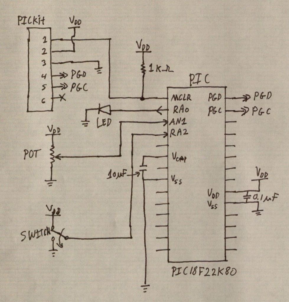
PIC microcontrollers are a highly useful and versatile component for various electronic projects. They are affordable and readily available. PIC microcontrollers are embedded systems that serve as the central control unit in a wide range of electronic applications. Their architecture...

Design a low-cost 4- to 20-mA receiver circuit for control loops using an analog-to-digital converter (ADC). The design of a low-cost 4- to 20-mA receiver circuit is essential in industrial applications for monitoring and controlling processes. This current loop standard...
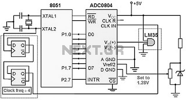
The ADC0804 converts the output voltages from the LM34/LM35 temperature sensors into digital signals that correspond to the measured temperature. These digital signals are then processed by the 8051 microcontroller. The temperature range for the LM35 sensor is from...
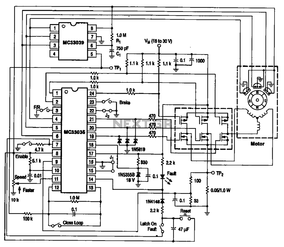
The brushless DC motor control circuit utilizing the MC33035 and MC33039 chips employs a combination of control circuits as illustrated in the figure. The primary components include the MC33035 motor control chip, the MC33039 brushless motor adapter, field effect...
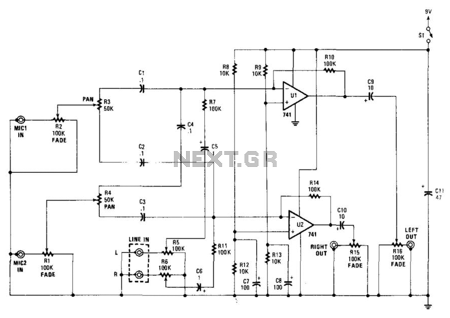
This stereo mixer features two mono mixers and a modification to the microphone inputs. When a microphone is in use, its output is directed to the microphone input of the circuit. The signal is then processed through resistors R1...