
Remote Control using DTMF

The remote control circuit described operates using radio frequency signals to manage electrical appliances, offering a significant advantage over traditional infrared systems, which are limited to line-of-sight operation. The core of this system is the DTMF (Dual-Tone Multi-Frequency) signaling method, which is commonly found in telephone dialers. The transmitter employs the UM91214B integrated circuit to generate DTMF tones, which are then frequency modulated and transmitted via an FM transmitter circuit.
The transmitter circuit is powered by a 9V supply that is stepped down to 3V using a zener diode regulator, ensuring the UM91214B operates within its specified voltage range. A quartz crystal oscillator provides the necessary timing for the DTMF generation, with a frequency of 3.58 MHz. The circuit utilizes a series of push-to-on switches that, when pressed, generate corresponding DTMF tones while simultaneously powering the transmitter, thus conserving battery life.
On the receiver side, an FM receiver module captures the transmitted DTMF signals. These signals are decoded by the KT3170 DTMF-to-BCD converter, which outputs binary-coded decimal signals corresponding to the pressed digits. The outputs from this IC are fed into toggle flip-flops constructed from CD4013B ICs, allowing for the control of multiple electrical appliances. Each flip-flop can toggle the state of a relay, which is connected to the appliance being controlled.
For scalability, the system can be expanded to control up to 12 appliances by utilizing additional circuitry, including a 4-to-16 line demultiplexer (IC 74154) and extra flip-flops. This flexibility allows the user to customize the remote control system according to their specific needs, making it a versatile solution for wireless appliance management. The entire setup is designed to be housed in a metallic enclosure to minimize interference and ensure stable operation.Here is a circuit of a remote control unit which makes use of the radio frequency signals to control various electrical appliances. This remote control unit has 4 channels which can be easily extended to 12. This circuit differs from similar circuits in view of its simplicity and a totally different concept of generating the control signals.
Usually remote control circuits make use of infrared light to transmit control signals. Their use is thus limited to a very confined area and line-of-sight. However, this circuit makes use of radio frequency to transmit the control signals and hence it can be used for control from almost anywhere in the house. Here we make use of DTMF (dual-tone multi frequency) signals (used in telephones to dial the digits) as the control codes.
The DTMF tones are used for frequency modulation of the carrier. At the receiver unit, these frequency modulated signals are intercepted to obtain DTMF tones at the speaker terminals. This DTMF signal is connected to a DTMF-to-BCD converter whose BCD output is used to switch-on and switch-off various electrical applicances (4 in this case).
The remote control transmitter consists of DTMF generator and an FM transmitter circuit. For generating the DTMF frequencies, a dedicated IC UM91214B (which is used as a dialler IC in telephone instruments) is used here. This IC requires 3 volts for its operation. This is provided by a simple zener diode voltage regulator which converts 9 volts into 3 volts for use by this IC.
For its time base, it requires a quartz crystal of 3.58 MHz which is easily available from electronic component shops. Pins 1 and 2 are used as chip select and DTMF mode select pins respectively. When the row and column pins (12 and 15) are shorted to each other, DTMF tones corresponding to digit 1 are output from its pin 7.
Similarly, pins 13, 16 and 17 are additionally required to dial digits 2, 4 and 8. Rest of the pins of this IC may be left as they are. The output of IC1 is given to the input of this transmitter circuit which effectively frequency modulates the carrier and transmits it in the air. The carrier frequency is determined by coil L1 and trimmer capacitor VC1 (which may be adjusted for around 100MHz operation).
An antenna of 10 to 15 cms (4 to 6 inches) length will be sufficient to provide adequate range. The antenna is also necessary because the transmitter unit has to be housed in a metallic cabinet to protect the frequency drift caused due to stray EM fields. Four key switches (DPST push-to-on spring loaded) are required to transmit the desired DTMF tones. The switches when pressed generate the specific tone pairs as well as provide power to the transmitter circuit simultaneously.
This way when the transmitter unit is not in use it consumes no power at all and the battery lasts much longer. The receiver unit consists of an FM receiver (these days simple and inexpensive FM kits are readily available in the market which work exceptionally well), a DTMF-to-BCD converter and a flip-flop toggling latch section.
The frequency modulated DTMF signals are received by the FM receiver and the output (DTMF tones) are fed to the dedicated IC KT3170 which is a DTMF-to-BCD converter. This IC when fed with the DTMF tones gives corresponding BCD output; for example, when digit 1 is pressed, the output is 0001 and when digit 4 is pressed the output is 0100.
This IC also requires a 3.58MHz crystal for its operation. The tone input is connected to its pin 2 and the BCD outputs are taken from pins 11 to 14 respectively. These outputs are fed to 4 individual D flip-flop latches which have been converted into toggle flip-flops built around two CD4013B ICs.
Whenever a digit is pressed, the receiver decodes it and gives a clock pulse which is used to toggle the corresponding flip-flop to the alternate state. The flip-flop output is used to drive a relay which in turn can latch or unlatch any electrical appliance.
We can upgrade the circuit to control as many as 12 channels since IC UM91214B can generates 12 DTMF tones. For this purpose some modification has to be done in receiver unit and also in between IC2 and toggle flip-flop section in the receiver.
A 4-to-16 lines demultiplexer (IC 74154) has to be used and the number of toggle flip-flops have also to be increased to 12 from the existing 4. 🔗 External reference
Related Circuits
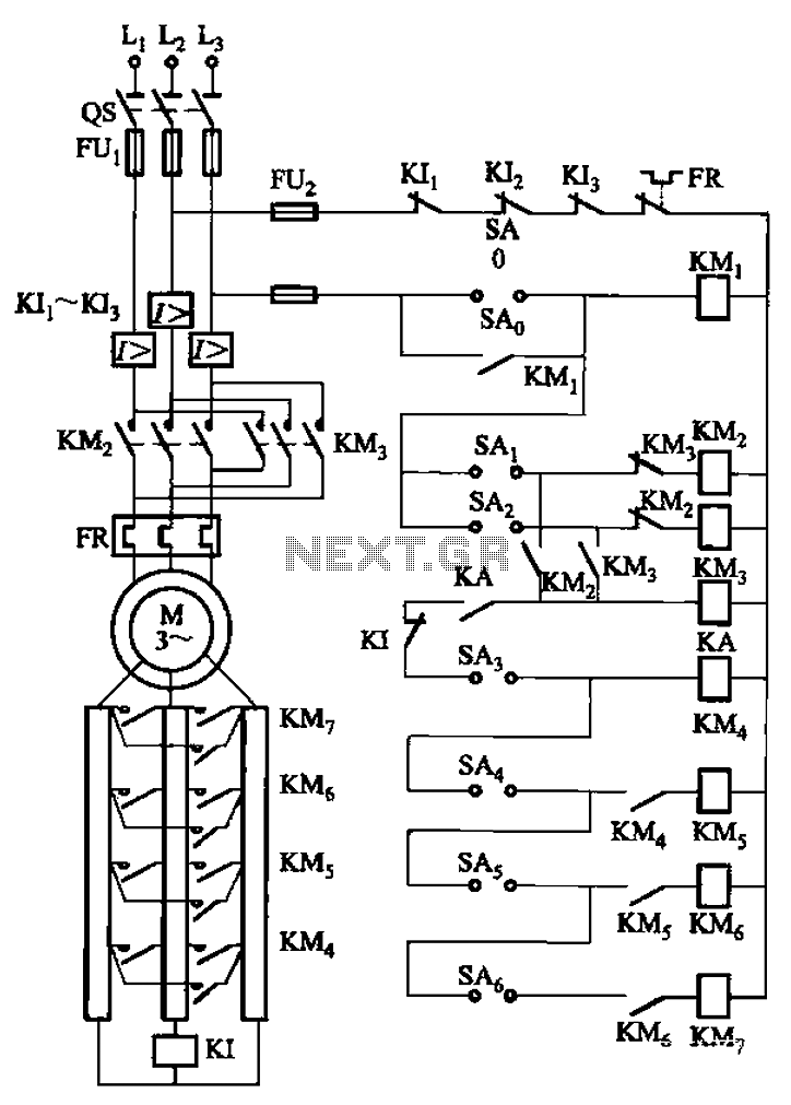
The circuit depicted in Figure 3-168 utilizes a controller for speed grading and reversing control. A reverse brake is connected to the rotor circuit through an overcurrent relay, labeled KI, for control. The current relay KIi to KI3 serves...
This circuit can control a small DC motor, like the one in a tape recorder. When both the points A and B are "HIGH," Q1 and Q2 are in saturation. Hence, the bases of Q3 to Q6 are grounded....
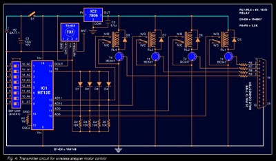
Stepper motors are widely used in applications such as process control, machine tools, and robotics. In particular, remote control of stepper motors is essential in robotics and process control. This document provides the circuit diagrams for both the transmitter...
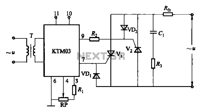
Adjustment potentiometer RP can modify the conduction angle of thyristor Vl, vz, thus altering the voltage applied across the load Rfz. The adjustment potentiometer (RP) serves a critical role in controlling the conduction angle of the thyristors Vl and vz within...
When running large-scale software or games, a computer's internal temperature can increase significantly, especially during hot summer months. Although the machine is equipped with a CPU and graphics card fan, poor hot air circulation prevents immediate removal of heat...
This temperature controller utilizes an LM135/235/335 temperature sensor and is designed to maintain a small environment at a warm or hot temperature. A schematic diagram is provided. The temperature controller circuit is centered around the LM135/235/335 series of temperature sensors,...