
Simple Temperature Controller

The temperature controller circuit is centered around the LM135/235/335 series of temperature sensors, which are precision devices capable of measuring temperature with high accuracy. The LM135, LM235, and LM335 differ primarily in their temperature range and output characteristics, allowing for flexibility in application depending on the specific requirements.
The circuit typically consists of the temperature sensor connected to an operational amplifier (op-amp) configured as a comparator. The op-amp compares the voltage output from the temperature sensor with a reference voltage, which can be adjusted to set the desired temperature threshold. When the temperature falls below this threshold, the op-amp output switches states, activating a relay or a solid-state switch to turn on a heating element.
Additional components may include resistors and capacitors for signal conditioning and stability, ensuring that the op-amp operates correctly within its linear region. A diode may be included for protection against back EMF if an inductive load, such as a relay, is used.
The power supply for the circuit should be stable, providing the necessary voltage for the sensor and the op-amp, typically in the range of 5V to 15V, depending on the configuration. The LM135/235/335 series sensors can operate over a wide range of temperatures, making them suitable for various applications, including greenhouses, incubators, and temperature-controlled storage.
In summary, the temperature controller circuit using the LM135/235/335 temperature sensor offers a reliable solution for maintaining a desired temperature in a controlled environment. The schematic diagram provides a visual representation of the connections and components involved in the circuit, aiding in the implementation and troubleshooting of the design.This temperature controller employs an LM135/235/335 temperature sensor, can be used to keep small environment warm or hot. Here is the schematic diagram:.. 🔗 External reference
Related Circuits
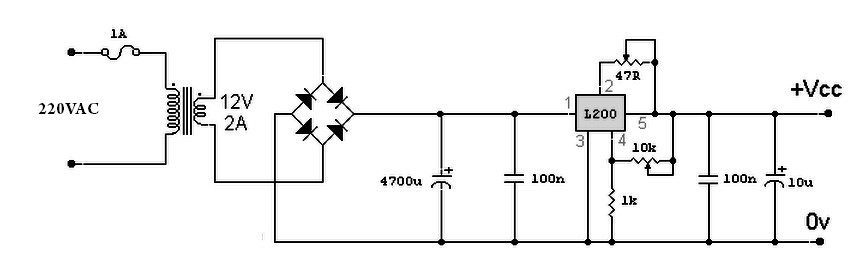
A variable power supply based on the L200 IC, where the output voltage is controlled by a 10K variable resistor. The output voltage ranges from approximately 3 to 15 volts, with a current output ranging from a minimum of...
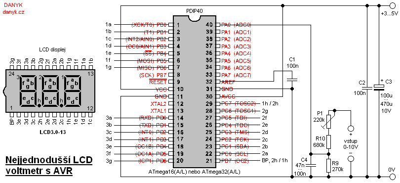
This is likely the simplest digital voltmeter utilizing an Atmel AVR microcontroller and an LCD display. The circuit is managed by a microprocessor IO1 - AVR Atmel ATmega16A, ATmega16L, ATmega16, ATmega32A, or ATmega32. A program is available for free...
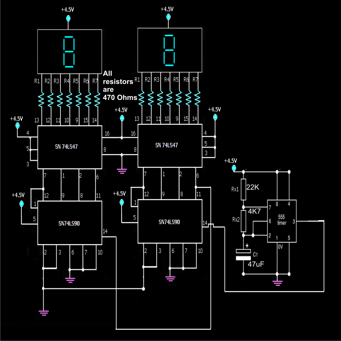
A simple frequency counter circuit can be easily constructed by any electronics enthusiast for its intended purpose. The circuit diagram was provided by Mr. Kapital through an order on Fiverr. The functioning of the circuit involves generating positive voltage...
This circuit is a simple analog multiplier. The operation of the circuit can be understood by considering A2 as a controlled gain amplifier. It involves components such as an analog multiplier, a log-antilog circuit, and a summing junction, along...
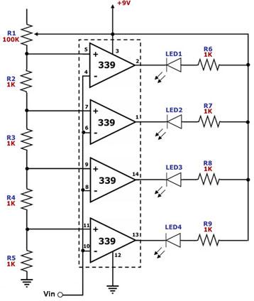
This circuit is designed as a simple LED bar graph voltmeter. Each operational amplifier in the LM339 quad package functions as a comparator, comparing the input voltage (Vin) to a series of fixed voltage levels that are proportional to...
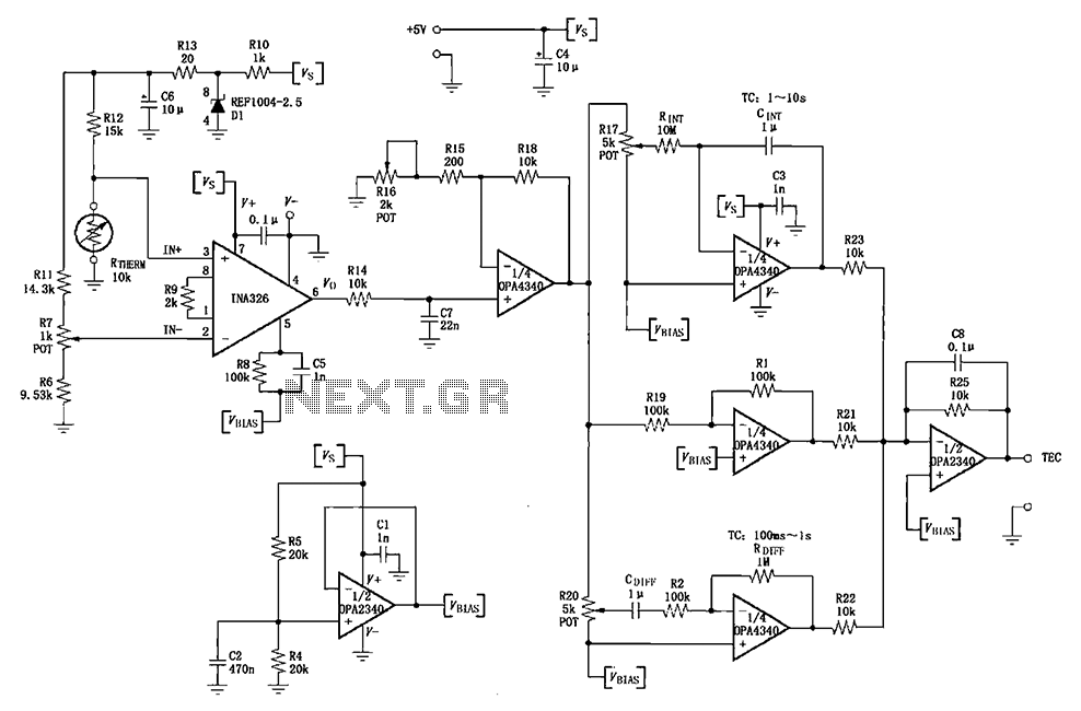
The INA326/327 forms a single power PID (proportional-integral-derivative) controller as illustrated in the temperature control loop. This circuit is primarily designed for temperature measurement and control. A thermistor, designated as RTHERM, detects temperature changes and converts them into an...