
A control circuit reversing braking and reverse grading speed control function

The circuit design integrates a controller that manages the speed and direction of a three-phase motor. The controller's functionality includes the capability to reverse the motor's direction, which is essential for applications requiring bidirectional operation. The reverse braking mechanism is crucial for safely decelerating the motor when a reverse command is issued. This is achieved by the reverse brake interfacing with the rotor circuit, ensuring that the motor quickly comes to a halt without causing excessive wear or damage.
The overcurrent relay, labeled KI, is a critical component for protecting the motor from excessive current conditions that could lead to overheating or damage. The relays KIi to KI3 are configured to monitor the current flowing through each phase of the motor. If the current exceeds a predetermined threshold, the relay will trip, disconnecting power to the motor and preventing potential failure.
In addition to overcurrent protection, the circuit includes a zero voltage relay, KA, which serves to protect the motor from undervoltage conditions. Undervoltage can lead to insufficient torque and may cause the motor to stall, potentially resulting in operational issues. The zero voltage relay monitors the supply voltage and will disconnect the motor if the voltage drops below a specified level, ensuring reliable operation and longevity of the motor.
Overall, this circuit design emphasizes safety and efficiency in motor control applications, incorporating essential protective measures to safeguard against common electrical faults. Circuit shown in Figure 3-168, which uses the controller SA grading speed and reversing control; reverse brake connected to the rotor circuit overcurrent relay KI to control; c urrent relay KIi ~ KI3 as a motor three phase overcurrent protection; zero voltage relay KA is used as undervoltage protection.
Related Circuits
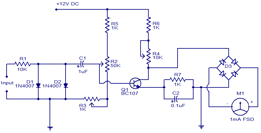
This is a simple circuit that functions as a tachometer. It operates as a frequency-to-current converter, transforming the incoming signal into a proportional current to drive the meter. The deflection on the ammeter correlates directly with the frequency of...

Useful for checking diodes, transistors, triacs, SCRs, resistors, and LEDs, this curve tracer should prove beneficial in the experimenter's lab. It displays the volt-ampere characteristic of a two-terminal device on an oscilloscope. This is a simple block diagram of...
The following circuit illustrates a stepper motor controller. This circuit is based on the PIC16F84A integrated circuit. Features: a transistor is utilized to drive the motor. The stepper motor controller circuit employs the PIC16F84A microcontroller, which serves as the central...
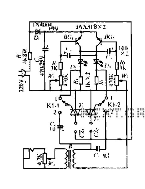
A 220V mains power supply is reduced using a control circuit designed by N. Guanidine D. Yi. The circuit features a spike Bode and provides a +9V voltage supply. It includes components such as a control port (G), a...

It is a self-oscillating voltage booster. It is relatively simple to build and it will allow you to use almost all the power in the battery, even when its voltage is low. The self-oscillating voltage booster is a circuit designed...
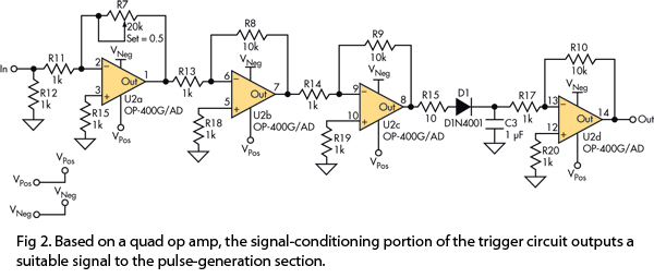
This version of the trigger circuit for the stop-motion camera system utilizes an electret microphone for sonic input, although it can be replaced with an LED and photodiode pair for optical triggering. A recent home-built project involved constructing a...