
RF-Radio Frequency 6

The potentiometer can be installed separately, if des ired, as well as R3 and Zener diode Interference from ignition noise pulse of the engine, it can cause various problems associated with radio communication equipment installed in the car. This circuit improves signal to noise ratio (S / N-ratio) was better, To connected between the output of the detector circuit with the audio input (if high impedance) or region of the impedance between the high dance audio section.
The automatic Gian control circuit also AGC with audio signal is simplest for compress to signal in the Radio receiver. It is ideal for short wave radio receiver used in areas with weak signals. You should adjust the master volume control dress until the desired signal intensity. While tuning the receiver to the station light, then gradually tuned to the power station and adjust the AGC pot until the pressure in the hearing as needed This circuit was designed as an aid to installers and maintainers of video systems.
It is basically a video sync separator (IC1) followed by a LED and buzzer driver (IC2, Q1 & Q2). In use, the device is connected to a video cable and if there is video present, the LED will flash at about 10Hz. If there is no video, the LED flashes briefly every couple of seconds. A buzzer can also be switched in to provide an audible indication. The buzzer is particularly useful when tracing cabling faults or trying to find a correct cable amongst many, where it is difficult to keep an eye on the LED.
Another use for the buzzer option is to provide a video fault indication. For example, it could be inserted in bridging mode, with switch S1 in high impedance mode (position 2) across a video line and set to alarm when there is no video present. If someone pulls out a cable or the video source is powered off, the alarm would sound. IC1 is a standard LM1881 video sync separator circuit and 75 termination can be switched in or out with switch S1a.
The other pole of the switch, S1b, turns on the power. The composite sync output at pin 1 is low with no video input and it pulses high when composite sync is detected It changes frequency as the incoming voltage, Frequency control. That, from the IC Oscillator NE566. IC phase locked loop circuit is in the nature of Demodulator. The output at Pin 7 and is connected to the IC op amp 741. Which is connected in a manner of Voltage-follower circuit. to the driver IC 566 to work. The voltage passing through the pin 6 of IC op amp, will be entered into a 5-pin of the IC 566. To control the frequency of leg 3 of the IC NE566. the multiplication of frequency equal to R1, C1, R2, C2. For the operation of the circuit stability. Therefore the value of R1 and C1 should be chosen to suit the frequency. Here is the circuit of an excellent direct coupled radio ideal for listening to near by stations. The circuit uses Q1 as a diode detector and first audio amplifier. The detection is across the first emitter base junction which operates as a diode. The base emitter capacitance provides the radio filtering. The resistor R1 is adjusted to obtain the least distortion with consistent volume. Transistors Q2 and Q3 also serve as audio amplifiers Here is the circuit diagram of a simple AM transmitter circuit that can transmit your audios to your backyard.
This circuit is designed with limited the power output to match the FCC regulations and still produces enough amplitude modulation of voice in the medium wave band to satisfy your personal needs. You will love this!. The circuit has two parts, an audio amplifier and a radio frequency oscillator. The oscillator is built around Q1 🔗 External reference
Related Circuits
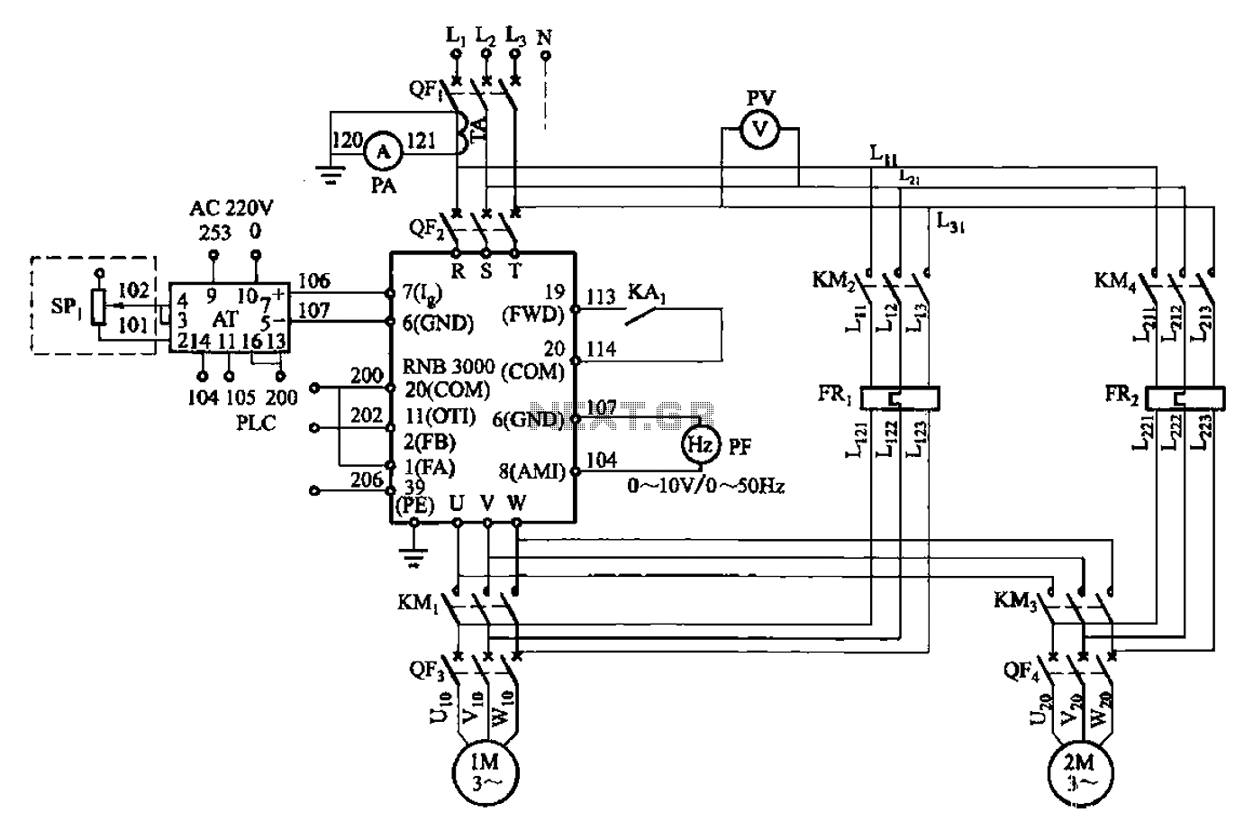
A control circuit for two motors, specifically for frequency control in a constant pressure water supply system, is illustrated in Figure 5-23. The circuit includes fault output terminals labeled 1 and 2, analog feedback current input terminals labeled 6...

Frequency converter schematic, frequency to voltage converter schematic, frequency to voltage converter using TR, voltage to frequency converter application. A frequency converter is an essential electronic circuit that transforms frequency signals into corresponding voltage levels or vice versa. The frequency...
This sine wave generator is adjustable between 15 Hz and 150 kHz. The circuit is essentially a Wien-bridge oscillator, featuring multiple capacitor selections. The sine wave generator operates on the principle of the Wien-bridge oscillator, which is known for producing...
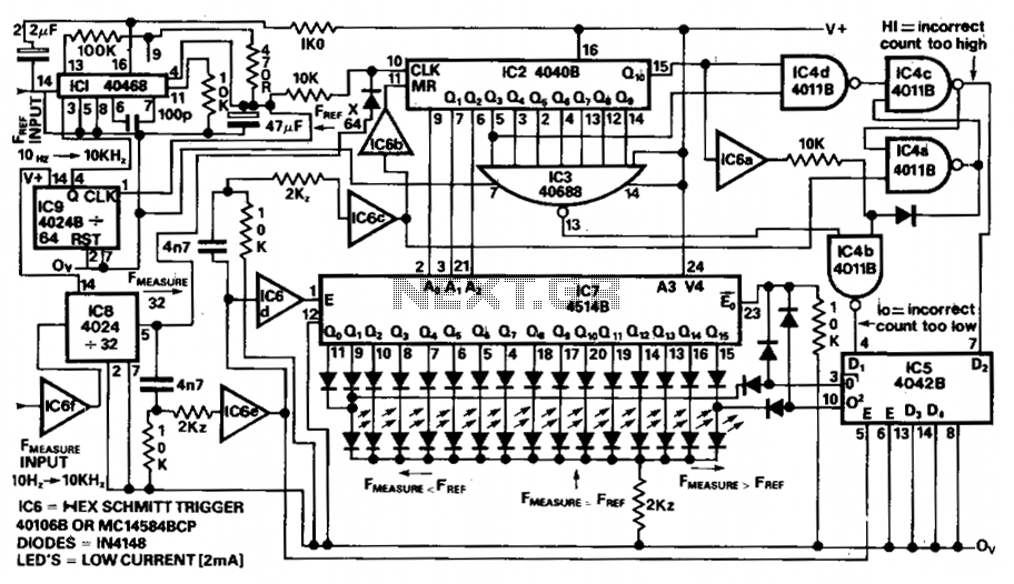
The circuit provides a clear LED display indicating positive or negative values in increments of 0.1%. A reference frequency is generated by multiplying the input frequency using PLLIC1 and divider IC9, resulting in an output frequency of 64 times...
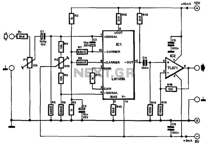
Often, the frequency of a signal must be doubled, and the modulator/demodulator chip LM1496 serves as an ideal basis for this application. From trigonometry, it is well known that 2sin(x)cos(x) = sin(2x) and sin^2(x) = 1 - cos^2(x). These...
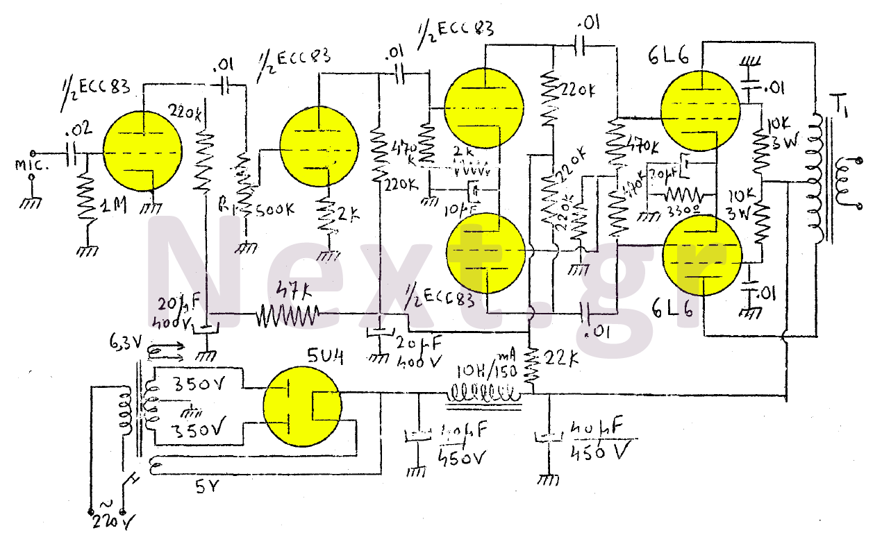
The amplifier in this design is rated at 30 Watts and is intended for use with a microphone. It is compatible with a crystal microphone and can be utilized for speeches, lectures, as a transmitter modulator, and in applications...