
Regulated Dual Power Supply Circuit Using Regulator IC

The dual power supply circuit operates by first converting the AC mains voltage to a lower AC voltage using transformer T1. This transformer has a primary winding rated for 230V and a secondary winding configured as 15-0-15 V, allowing for the generation of both positive and negative voltages. The center tap of the transformer provides the ground reference for the circuit.
Following the transformer, the AC voltage is rectified to DC using a bridge rectifier configuration formed by diodes D1, D2, D3, and D4. This arrangement allows for full-wave rectification, ensuring that both halves of the AC waveform contribute to the output voltage. The rectified voltage is then smoothed using filtering capacitors C1 and C2, which reduce ripple and provide a more stable DC voltage.
Decoupling capacitors C3, C4, C7, and C8 are included in the design to filter out high-frequency noise that may affect the performance of the voltage regulators. These capacitors are critical in maintaining the stability of the output voltage under varying load conditions.
The LM7812 and LM7912 voltage regulator ICs are central to this circuit, providing regulated outputs of +12V and -12V, respectively. The LM7812 is designed to maintain a constant output voltage despite variations in input voltage or load conditions, while the LM7912 provides the inverse regulation for the negative voltage. Each regulator requires a minimum input-to-output voltage differential to function correctly, which is typically around 2V.
To ensure safe operation, a fuse (F1) rated at 500mA is included in the circuit. This fuse protects the circuit from overcurrent conditions that could cause damage to the components.
Finally, it is important that the capacitors used in this circuit, specifically C1, C2, C5, and C6, are rated for at least 50V to withstand the potential voltage spikes that may occur in the circuit, ensuring reliability and longevity of the power supply.The circuit is use to regulation dual power supply that provides +12V and -12V from the AC mains. A power supply like this is a very essential tool on the work bench of an electronic hobbyist. This is the figure of the schematic of the circuit. This circuit is built by LM7812 and LM7912 for the voltage regulator IC. The transformer T1 steps down t he AC mains voltage and diodes D1, D2, D3 and D4 does the job of rectification. Capacitors C1 and C2 does the job of filtering. C3, C4, C7and C8 are decoupling capacitors. IC 7812 and 7912 are used for the purpose of voltage regulation in which the former is a positive 12V regulator and later is a negative 12V regulator. The output of 7812 will be +12V and that of 7912 will be -12V. Transformer T1 can be a 230V primary; 15-0-15 V, 1A secondary step-down transformer. Fuse F1 can be a 500mA fuse. Capacitor C1, C2, C5 and C6 must be rated at least 50V. 🔗 External reference
Related Circuits
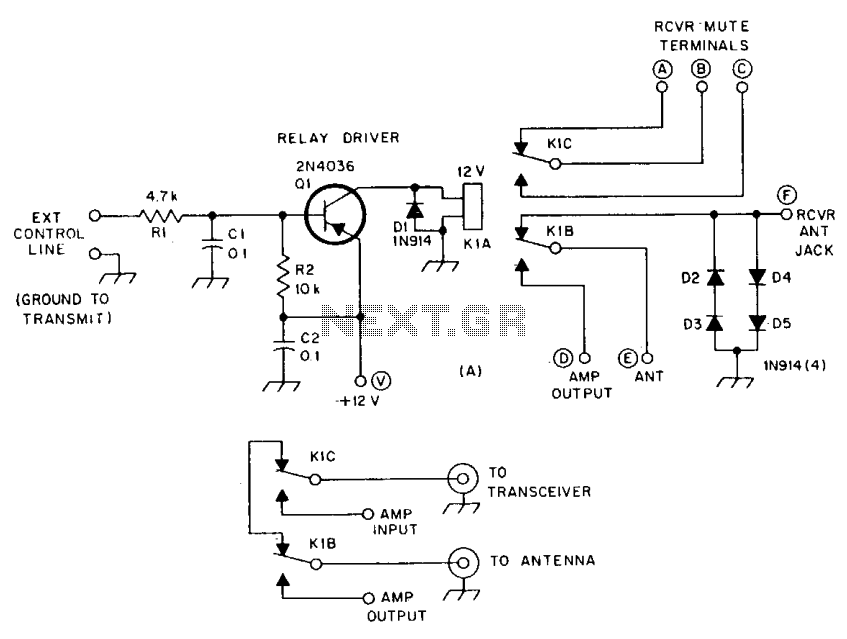
R1 and R2 are carbon composition resistors labeled as Va or Vi. K1 is a 12 V DPDT DIP relay. Illustration A demonstrates the connection of the relay contacts for use with a separate transmitter-receiver combination. The circuit is...
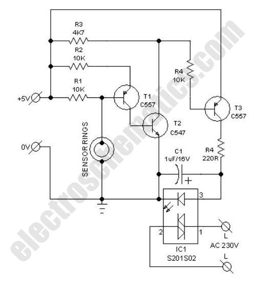
This compact water sensor alarm circuit emits a loud warning sound when a humidity sensor detects the presence of water. The circuit utilizes the low-power comparator LM1801 from National Semiconductor. A fixed reference voltage for the integrated circuit is...
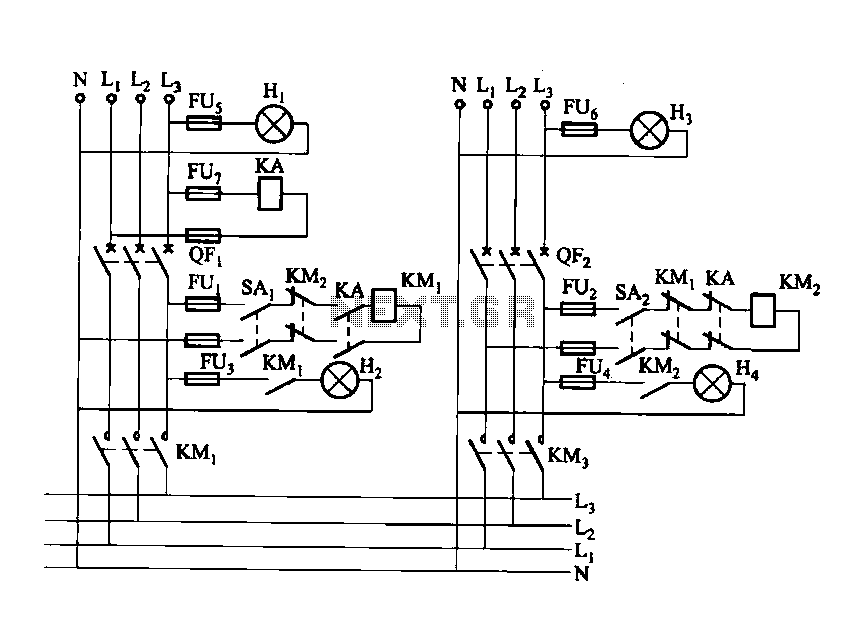
Dual power automatic recovery means one power supply and one standby power supply. When the main power supply is turned off, the standby power supply is automatically activated. Once the main power supply is restored, the system automatically exits...
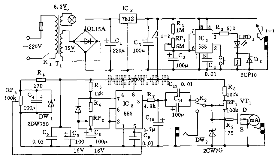
The information apparatus includes a buck rectifier power supply providing Vdd at +12V, a timing circuit, a multivibrator, and the output from the first amplifier. The components R1, RP1, and C3 are used to initiate timing, with the timing...
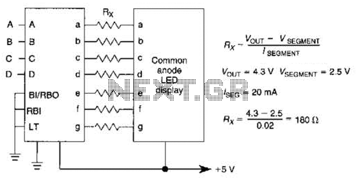
An IC1, such as the 7447, drives a common anode 7-segment LED display. The current-limiting resistor R must restrict the segment current to the rated value at the maximum supply voltage. A sample calculation is provided. The 7447 integrated circuit...
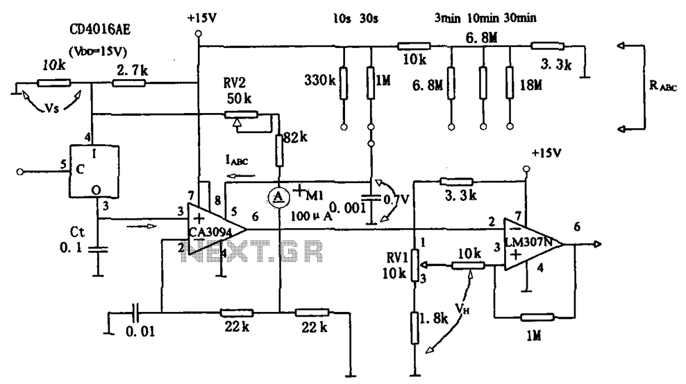
The long timer circuit utilizes an operational amplifier, specifically the CA3094, to control the discharge formula for extended timing. This is typically achieved by adjusting the variable resistor RV1, which alters the timing duration to meet specific requirements. The long...