
Remote Controlled Alarm circuit

The remote-controlled alarm circuit designed with the TSOP1736 is an innovative solution for enhancing safety and convenience, particularly for elderly individuals. The TSOP1736 is an infrared receiver module that effectively detects signals from a compatible remote control. This application allows the user to activate an alarm system from a distance, providing immediate assistance when needed.
The circuit typically includes several key components: the TSOP1736 infrared receiver, a microcontroller for processing the received signals, an alarm module such as a buzzer or siren, and a power supply. When the remote control button is pressed, the TSOP1736 receives the infrared signal and sends it to the microcontroller. The microcontroller interprets the signal and activates the alarm module, which emits a sound to alert caregivers or family members.
In addition to the alarm function, the circuit can be enhanced with features such as LED indicators to show the status of the system, or a more complex interface that allows for different alarm tones depending on the urgency of the situation. The wiring for the calling bell switch should be carefully routed to ensure easy access for the user while maintaining safety standards.
This setup not only promotes independence for the elderly but also ensures that help is readily available at the push of a button. Proper installation and testing of the system are crucial to ensure reliable operation and to avoid any potential issues.A very interesting remote controlled alarm circuit using TSOP1736. Routing of an electric cable to attach a calling bell switch near the bed of an old age/. 🔗 External reference
Related Circuits
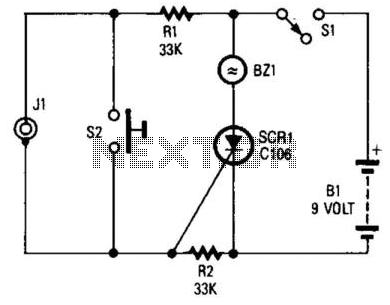
If you choose to create your own moisture sensor, this foil pattern will be useful. A sensor connected to J1 activates CR1, which sounds buzzer BZ1. The sensor consists of a printed circuit board (PCB) foil pattern grid. Multiple...

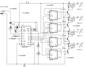
Remote Control Mains Switch The remote control mains switch is a device designed to control the power supply to electrical appliances from a distance, typically utilizing a wireless remote control. This switch can be integrated into various applications where remote...
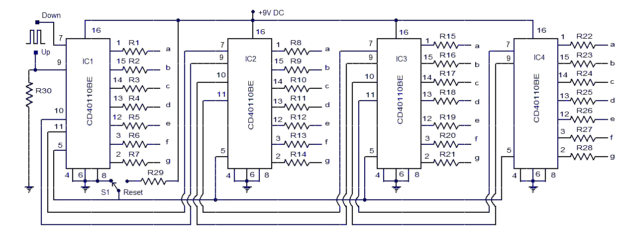
This circuit diagram illustrates a simple up/down counter suitable for various applications. It utilizes the CD40110BE IC, a CMOS decade up/down counter. Common cathode seven-segment displays are connected to the outputs of each IC. The display connected to IC1...
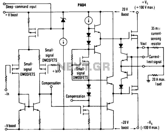
This circuit from Apex Microtechnology can deliver 180 V peak-to-peak at 90 kHz into a 4-ohm load. The PA04 can deliver 400 watts RMS into an 8-ohm load with low total harmonic distortion at frequencies exceeding 20 kHz. The circuit...
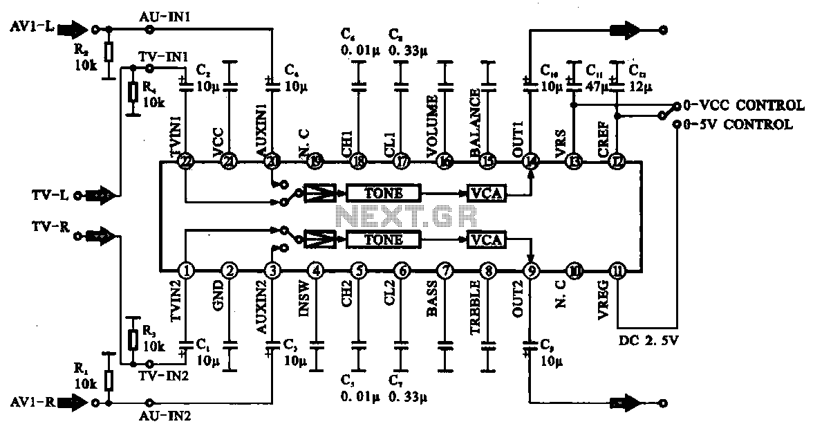
Audio signal control circuit. It illustrates a typical audio signal control circuit where two audio signals enter the integrated circuit through switching and tone controls (treble and bass), subsequently adjusting the output sent to the audio power amplifier. The audio...
The following circuit illustrates a DTMF (Dual Tone Multi-Frequency) Remote Domestic System Control Circuit Diagram. Features: DTMF signals can be transmitted over a radio. The DTMF Remote Domestic System Control Circuit is designed to enable control of domestic appliances through...