
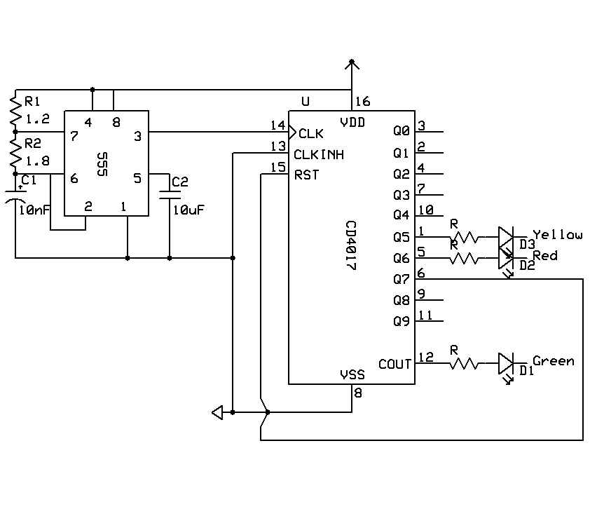
Timer With On-Off Delay

The 555 timer is a versatile device widely used in various timing applications. In this specific configuration, the circuit operates in monostable mode, where the timer generates a single output pulse in response to an external trigger. The duration of the pulse, which corresponds to the "on" time, can be adjusted by varying the resistance and capacitance in the timing network.
The circuit typically consists of a 555 timer IC, a resistor (R), a capacitor (C), and a switch to initiate the timing sequence. When the switch is closed, the capacitor begins to charge through the resistor, and the output of the 555 timer transitions from low to high. The time period for which the output remains high is determined by the formula T = 1.1 * R * C, where T is the time in seconds, R is the resistance in ohms, and C is the capacitance in farads.
To create an off delay, the circuit can be designed such that once the output goes high, it remains high for the predetermined time before returning to low. This can be particularly useful in applications where a device needs to be activated for a specific duration before shutting off automatically.
In addition to the basic components, it may also include diodes for protection against reverse polarity and to ensure proper discharge of the capacitor. The output can be used to drive other devices, such as LEDs, relays, or other electronic components, making this circuit highly adaptable for various applications in automation and control systems.// 555 Timer With On Off Delay Circuit Here is a timer circuit using common IC 555. The circuit is designed to facilitate time adjustment of both. 🔗 External reference
Related Circuits
The following circuit illustrates a BC547 transistor used in an output relay delay audio amplifier circuit diagram. Features include the immediate disconnection of the speaker when the... The BC547 transistor is a widely utilized NPN bipolar junction transistor, often employed...
A timer is being developed for circuit training or boxing training. The timer does not require any external input, except for a reset function. The project can be simplified using a microcontroller, such as the PIC12F635, which is cost-effective...
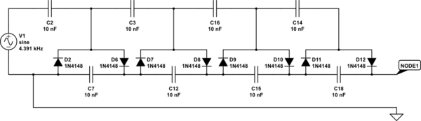
The output of the transformer has been calculated to be 125 times higher than the input, based on the ratio of 1000 to 8. Given an input of 12V, the expected output should be 1500V, although there is some...
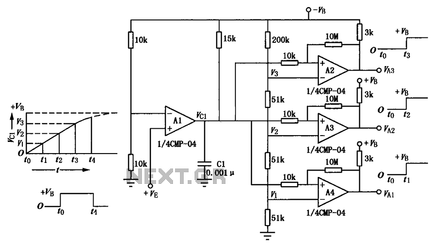
A multi-stage delay circuit is presented in this schematic. The operational amplifiers are configured as comparators. Operational amplifier A1 operates when the voltage at the inverting input exceeds + VE. As the voltage at the inverting input of operational...
This timer is designed for individuals seeking to achieve a tan while minimizing excessive exposure to sunlight. A rotary switch allows the user to set the timer based on six classified photo-types. A photoresistor adjusts the preset time value...
This circuit gradually switches the internal lights of a car on and off. The delay time can be adjusted by changing the values of the 10k and 4.7M resistors, as well as the capacitor. The circuit operates by utilizing a...