
REPAIRING THE DSC/DRC CURRENT SOURCES

The DSC Sine and DRC Random vibration controller cards are designed for precise control and monitoring of integrated accelerometers in various applications. The current sources, providing an output of 4 mADC, ensure that the accelerometers receive consistent power, which is critical for accurate measurements. The voltage-doubler circuit is a key component, efficiently converting the 12 VDC from the computer power supply to approximately 20 VDC. This higher voltage is necessary for the operation of the driver integrated circuit, which plays a crucial role in managing the power distribution to the accelerometers.
The use of the 78L018 voltage regulator is essential for maintaining a stable output of 18 VDC, protecting the sensitive components from voltage fluctuations that could affect performance. The integration of NPN and PNP transistors in the current source design allows for effective control of the current flow, with the 2N3904 NPN transistor acting as a switch that is controlled by the computer data bus. The subsequent activation of the 2N3906 PNP transistor ensures that the required current is supplied to the accelerometers.
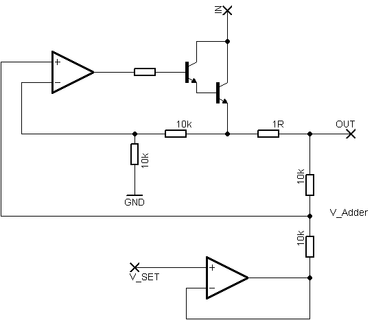
The short-circuit protection feature enhances the reliability of the circuit by preventing damage under fault conditions. However, careful attention must be paid to avoid applying excessive voltage to the input pins, as this can compromise the integrity of the transistors. Regular testing with a multimeter is recommended to ensure the functionality of the current sources and the overall health of the circuit. The accompanying schematic diagram provides a comprehensive view of the circuit layout, facilitating troubleshooting and further design modifications if necessary.The DSC Sine and DRC Random vibration controller cards have current sources on the two inputs available for powering integrated accelerometers without requiring external power supplies. These current sources have an 18 VDC open circuit voltage and output 4 MADC into the input pins. The 18 VDC is generated by a voltage-doubler circuit operating fro m the 12 VDC computer power; it is a TCS429CPA driver I/C ( U22 on the DSC and U20 on the DRC ) and associated diodes and capacitors. The circuit outputs about 20 VDC which is regulated down to 18 VDC by the 78L018 regulator I/C ( U23 on the DSC and U37 on the DRC ).
Each 4 MA current source consists of a 2N3904 NPN transistor ( Q1 and Q3 ) connected to the computer data buss which turns on the 2N3906 PNP current source transistor The inputs are short-circuit protected, but excess voltage applied to the input pins could damage the transistors. They can be checked with a meter in the usual way. Refer to the schematic diagram below for circuit details: 🔗 External reference
Related Circuits
This circuitry facilitates the connection between the computer's Z RS-23 serial interface and the current ring circuitry. It converts the voltage signal of the transmission into a current signal of 20 mA, achieving a maximum speed of 1200 bits....
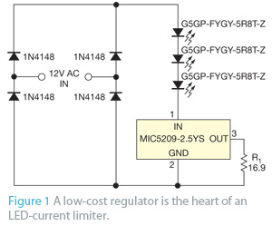
When an application does not require PWM (pulse-width-modulated) dimming or controlled frequency operation, the primary concern may be preventing excessive current that could damage or destroy LEDs. A simple LED current limiter can be created using a common low-dropout...
The LM317 is capable of providing extremely good load regulation, but a few precautions are needed to obtain maximum performance. For best performance, the programming resistor (R1) should be connected as close to the regulator as possible to minimize...
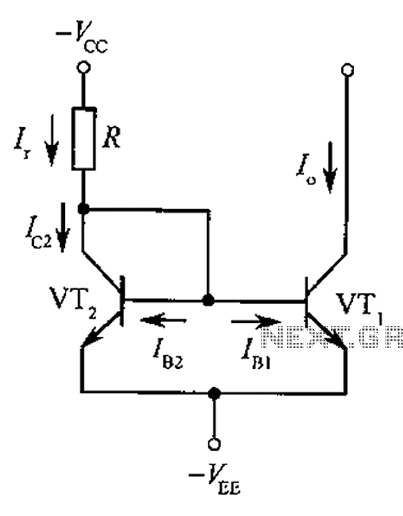
The circuit depicted is a mirror substantially constant current source circuit, in which transistors VT1 and VT2 are matched to each other. The figure illustrates that the current through Ir is equal to Ic2 plus the sum of base...
Rsense will cause Q2 to conduct when a threshold of approximately 0.65V is reached. Rbias will determine the extent of this limitation, although this aspect remains unclear. Particularly, if Rsense is positioned on the high side, simply activating Q2...
The impedance of these current generators is essentially infinite for small currents, and they maintain accuracy as long as VIN is significantly greater than VOS and IO is much higher than I bias. The source employs a FET to...