
The computer Z RS-23 serial interface current loop circuit diagram

The described circuitry is integral for interfacing between a computer's RS-232 serial port and a current loop signaling system. The conversion from voltage to current is crucial for maintaining signal integrity over longer distances, where voltage signals may degrade. The current loop operates at 20 mA, which is a standard for many industrial applications, ensuring compatibility with various devices.
The light-coupled device IC3 serves as an optical isolator, providing electrical isolation between the computer's circuitry and the current loop. This isolation is vital for protecting the computer from potential voltage spikes or noise from the current loop, ensuring reliable operation. T1, which is part of the receiving port interface, works in conjunction with IC3 to facilitate the conversion process while maintaining signal fidelity.
T2 and T3 are likely transistors or similar components that are responsible for driving the current loop. These components are configured to switch on and off in response to the incoming signals, thus generating the required 20 mA current. The design must account for the maximum bit rate of 1200 bits per second, ensuring that the components can respond quickly enough to maintain data integrity.
Overall, the circuit design must be carefully optimized to handle the requirements of both the RS-232 standard and the current loop specifications, ensuring robust performance across various operating conditions. Proper layout and component selection are essential to minimize signal degradation and ensure reliable communication between the computer and the connected devices.This circuitry is used for the joggle between computer Z RS-23 serial connecting current ring and current ring circuitry, it can transform the voltage semaphore of transmission into the current semaphore with 20 mA, the biggest speed can reach 1200 bits. Light-coupled device IC3, T1 make up receiving port connecting interface circuit, T2, T3 constitute tran..
🔗 External reference
Related Circuits

The circuit consists of a PIC microcontroller, an in-circuit serial programming (ICSP) interface, an RS232 level translator, and an HD44780 LCD display. Initially, a scrolling message is shown using the show_intro function. When a serial input is detected, the...
A PoE Plus power level of 30 W can be achieved by utilizing an external MOSFET along with a controller that is compatible with the older standard. Power over Ethernet (PoE) technology enables the delivery of electrical power along with...
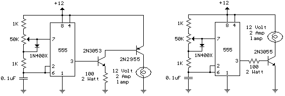
The schematic diagram illustrates a 12 Volt Car Lamp Dimmer Circuit Design utilizing a 555 Timer. This circuit can be employed to dim a standard 25-watt lamp. The 12 Volt Car Lamp Dimmer Circuit utilizes a 555 Timer in astable...
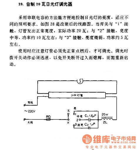
A homemade 20W fluorescent lamp dimmer utilizes a series capacitor connection to effectively control the brightness of fluorescent lamps, allowing for adaptability to various lighting requirements. In the modified circuit diagram (Figure 28), when the switch is set to...

Pins 1 and 5 on this amplifier are trim pins and are not utilized in the circuit. When not in use, it is necessary to leave them floating. In electronic amplifier circuits, trim pins are often included for calibration or...

A simple 3-way crossover, intended for triamping Hi-Fi systems. This is a conventional 12dB / Octave unit, and cannot be expected to have the same performance as a Linkwitz-Riley aligned filter network. It will still be a vast improvement...