
Reset from Multiple Power Supplies

This circuit design is critical for ensuring reliable operation in processor-based systems, especially in environments where power supply fluctuations are common. The use of the TL7705A voltage supervisor provides a robust mechanism for monitoring the +5 V rail, which is essential for processor functionality. The reset pulse generated by this IC is adjustable through the capacitor at pin 3, allowing for customization based on the specific timing requirements of the application.
The integration of TL7712A supervisors for monitoring the +12 V and -12 V supplies adds a layer of reliability, ensuring that all critical power rails are actively supervised. The open collector configuration of the outputs necessitates careful consideration of pull-up and pull-down resistor values to ensure proper logic levels are maintained during operation.
The level shifting functionality provided by the JFET transistor T1 is particularly noteworthy, as it allows for safe interfacing between different voltage levels, preventing potential damage to the ICs involved. This feature is essential in mixed-voltage systems where components operate at different logic levels.
Overall, this voltage supervision circuit is a well-thought-out design that enhances the reliability of processor-based systems by ensuring that the processor is reset appropriately under brown-out conditions, thereby preventing erratic behavior and potential system failures.Processor based systems usually require a voltage supervisor chip to produce a clean reset pulse to the processor whenever a brown-out` condition of the power supply is detected. More complex designs employing multiple power supplies can be unreliable if some of the supplies are not supervised.
The circuit described here monitors all the supply ra ils in the system (here +12 V, 12 V and +5 V) and provides a reset pulse to the processor whenever it detects any are not within tolerance. IC1 (TL7705A) generates a processor reset if the 5 V rail falls below 4. 55 V. The value of the capacitor fitted to pin 3 defines the reset pulse width td according to the formula: td = 12.
CT 3 103 With CT in µF the value for td is given in µs. A capacitor of 100 nF for example, will produce a reset pulse of around 1. 2 ms. Pin 6 (RESET) outputs an active-high pulse and Pin 5 (RESET) an active-low pulse. The outputs are open collector types so an external pull-down and pull-up resistor (respectively) is required. The RESIN input (Pin 2) of IC1 is driven from two TL7712A supervisors monitoring +12 V (IC2) and 12 V (IC3).
The TL7712A generates a reset when the supply voltage falls below a threshold level of 10. 8 V. The open collector output RES (Pin 5) of IC2 is connected to the RESIN pin of IC1 and pulled up to 5 V via a 100 k resistor. The open collector output of IC2 can be directly connected to the reset input of IC1 but the output of IC3 must be connected via a level shifting device before it can be connected to the reset input of IC1 because the voltage level at the output of IC3 goes negative.
JFET transistor T1 is used to perform the necessary level shifting. The JFET turns off when the voltage at its gate-source junction is between 2. 5 V and 6 V. When IC3 is issuing a reset signal the RES output (pin 6) will go up to ground potential and cause T1 to conduct and trigger a reset of IC1. At all other times the RES output of IC3 will be pulled to a minus voltage via the 100 k resistor which then causes T1 to stop conducting and release the reset.
A manual reset push button can also be connected to RESIN of IC1 if required. The SENSE input (Pin 7) of the TL77xx chips is connected to the positive supply rail. The reference input (pin 1) is fitted with a 100 nF capacitor to reduce the effects of fast transients. 🔗 External reference
Related Circuits
Since my page was first posted, I have received a number of emails asking about a high current power supply. I looked around, but couldn’t find one that was suitable. So, I designed this. It is a linear supply,...

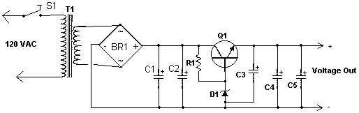
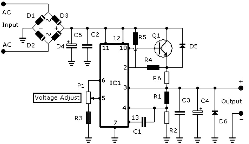
The adjustable power supply can be reconfigured by changing the value of V2 and enhancing other components as needed. The output voltage is calculated using the formula Vnm = 1.25 (1 + R2/R^). Additionally, R2 can be modified as...
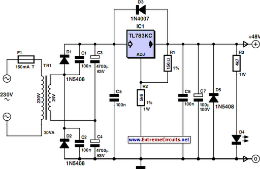
48 V phantom powering has become the standard for professional condenser microphones. The supply voltage is applied over both wires of the balanced screened cable via two 6.8 kΩ resistors. The absolute value is not critical, as a variation...
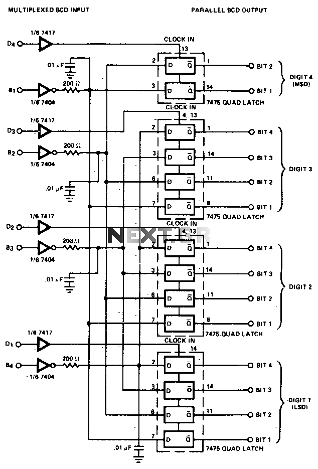
The converter is composed of four quad bistable latches that are activated in the correct sequence by the digit strobe output from the LD110. The complemented outputs (Q) of the quad latch set represent the state of the bit...
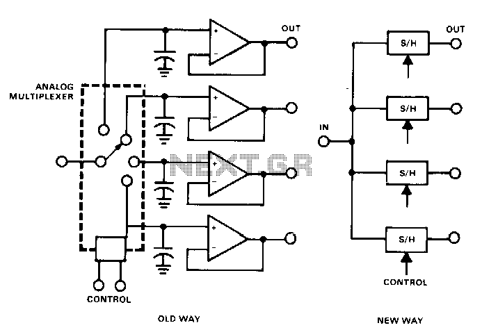
This circuit reconstructs and separates analog signals that have been time-division multiplexed. The conventional method has several restrictions, particularly when a short dwell time and a long, accurate hold time are required. The capacitors must charge from a low-impedance...
DC power supply 3-30V 3-30V 3A stabilized power supply. Go to that page to read the explanation about the above power supply related circuit diagram. The DC power supply described is a versatile device capable of providing a stable output...