
Configurable Power Supply Circuit

The adjustable power supply circuit is designed to provide a variable output voltage based on the configuration of specific components. The core of this circuit typically employs a voltage reference and an operational amplifier (op-amp) in a feedback arrangement. The formula for the output voltage, Vnm = 1.25 (1 + R2/R^), indicates that the output voltage can be adjusted by varying the resistor R2, while R^ represents a fixed resistor in the circuit.
The voltage reference, often a precision device, ensures that the output remains stable despite variations in load current or input voltage. The op-amp amplifies the difference between the reference voltage and the feedback voltage derived from the output, thus maintaining the desired output level.
To enhance the performance of the adjustable power supply, other components may need to be beefed up. This can include capacitors for filtering, which reduce ripple voltage and improve transient response, as well as inductors or additional resistors that may be used to stabilize the output or adjust the response time of the circuit.
In practical applications, the ability to adjust R2 allows for a wide range of output voltages, making the power supply versatile for various electronic projects. Proper selection of R2 is crucial, as it directly influences the output voltage range and the stability of the supply. Additionally, ensuring that all components are rated for the intended load current and voltage is essential for reliable operation.
Overall, this adjustable power supply circuit is a fundamental design that can be tailored for specific requirements by modifying key components, thus providing flexibility for different electronic applications. The adjustable supply can easily be reconfigured by altering the value of V2 and beefing up some other components, as is necessary. The output voltage is given by Vnm = 1.25 (1 + R2!R^). R2 can be changed, as is necessary.
Related Circuits
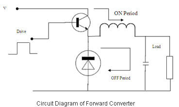
Switched Mode Power Supplies (SMPS) are categorized as DC to DC converters and DC to AC converters. Switched Mode Power Supplies (SMPS) are essential components in modern electronic devices, providing efficient power conversion from one form to another. The primary...
This device is a combination digital clock timer and solar panel charge controller designed to maintain a deep cycle battery from a solar panel. The timer output controls a 12-volt load for a 32-minute interval each day. The start...
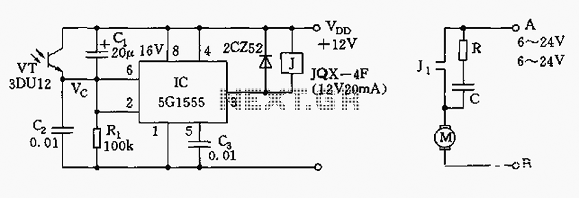
The control circuit consists of an NE555 timer and a phototransistor, along with resistors R1, capacitors C1 and C2, among other components. The photodiodes 3DU12 respond to sunlight by decreasing their resistance, which causes the voltage at the 555...
This is a low-power voltmeter circuit suitable for alternative energy systems operating on 12-volt and 24-volt batteries. The voltmeter features an expanded scale design, allowing it to display small voltage increments within the 10 to 16-volt range for 12-volt...
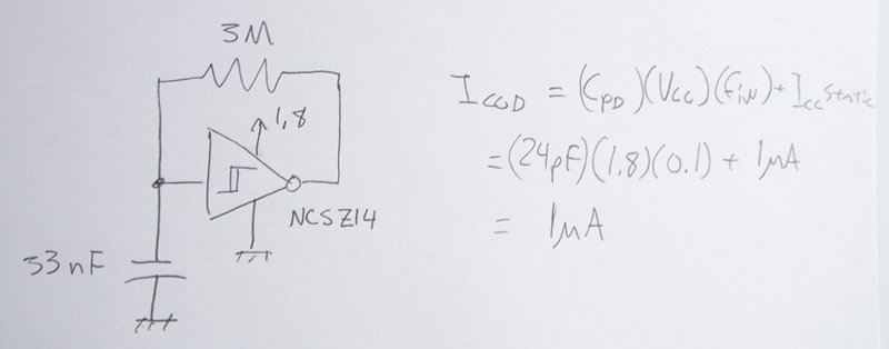
The power supply varies, and the circuit must operate at under 10 µA of current (excluding the capacitor charging). It triggers a Silicon Controlled Rectifier (SCR) every 10 to 30 seconds as long as the power supply is above...
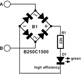
The modem off indicator is designed specifically for avid Internet users. The circuit for this indicator is remarkably simple, and its simplicity may lead to significant cost savings by providing a clear visual indication of whether the telephone line...