
resistance Replicate thermistor behavior for second sensor

To achieve the desired functionality of the secondary sensor board while maintaining the thermal protection provided by the speed control, a careful design approach must be employed. The thermistor, as a temperature-sensitive resistor, varies its resistance based on temperature changes. In this case, a 10K NTC (Negative Temperature Coefficient) thermistor is used, where resistance decreases as temperature increases.
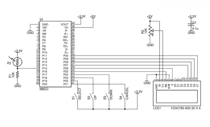
The first step involves creating a voltage divider circuit to read the thermistor's resistance. This can be accomplished by connecting the thermistor in series with a fixed resistor (R1) to form a divider. The voltage across the thermistor can be measured and converted to a temperature reading using an analog-to-digital converter (ADC). The value of R1 should be chosen to match the thermistor's nominal resistance at the expected operating temperature, typically around 10K at 25°C.
To facilitate the dual functionality of reading the thermistor for both the display and the speed control, an operational amplifier (op-amp) can be utilized. The op-amp can buffer the voltage reading from the voltage divider, allowing it to drive both the segment display and the speed control input without affecting the measurement accuracy. This configuration ensures that the speed control receives a stable and accurate representation of the thermistor's resistance.
Additionally, to ensure that the speed control's thermal protection remains effective, it is crucial to isolate the two circuits. This can be achieved by using an isolation amplifier or a second op-amp configured as a non-inverting buffer. This approach allows the thermistor's output to be replicated accurately for both the speed control and the display without interference from one circuit to the other.
In summary, the design should include a voltage divider to read the thermistor, an op-amp to buffer the signal, and isolation techniques to ensure that both the segment display and the speed control receive the necessary temperature data without compromising functionality. This comprehensive approach will enable effective temperature monitoring while preserving the thermal protection capabilities of the speed control unit.An R/C electric motor that has a 10K thermistor sensor built into it, which is connected to a speed control that has basic thermal protection. I would like to build a secondary sensor board that displays the temperature on a segment display, but I still want to pass it through to the speed control so that it still has thermal prot
ection. The issue I`m having is that the thermistor is only connected to ground on one end, no other reference potential, so I plan to read it with a voltage divider. This means I can`t just pass the end of the thermistor back through to the speed control, which may have its own voltage divider.
Is there a way I can replicate the resistance of the thermistor to two different read circuits expecting a variable resistance 🔗 External reference
Related Circuits
This issue features articles on various measurement and sensor-related embedded design projects. Readers are encouraged to attempt similar projects and share their results. Starting on page 14, Petre Tzvetanov Petrov describes a multilevel audible logical probe design. Petrov notes...

The sensitivity of the circuit can be adjusted using potentiometer P1 to avoid responding to ambient noise levels. Diodes D1 and D2 rectify the signal, while capacitor C4 provides smoothing. When the voltage across C4 exceeds 0.5 V, transistor...
A distance sensor would be a beneficial addition to Mindstorms robots; however, ultrasonic sensors tend to be bulky and power-intensive. Simple infrared methods, like those used in radar cars, can detect obstacles but do not provide accurate distance measurements....
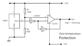
This is a basic overview of the LM35 temperature sensor, which is interfaced with an operational amplifier (op-amp) to boost its output. The LM35 provides a high output voltage when it detects high temperatures. The output can be utilized...
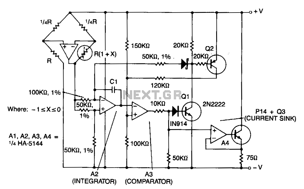
This circuit features amplifier A1 as a sensor amplifier configured in a bridge arrangement. Amplifiers A2 and A3 are set up as a voltage-to-frequency converter, while A4 functions as the transmitter. The entire sensor/transmitter operates directly from a 4...
The SP1481E, SP1485E, SP1490E, and SP1491E series transceivers, combined with the SP6652 high-efficiency, high-frequency current mode PWM buck regulator, facilitate the creation of an isolated RS-485 interface capable of providing up to 2kVrms isolation. This configuration supports CAN communication...