
GP2D12 distance sensor

The described circuit effectively integrates the GP2D12 distance sensor with the RCX, addressing the limitations of previous designs by utilizing a capacitor to manage power requirements. The design prioritizes simplicity and efficiency, ensuring that the sensor can operate within the constraints of the RCX system while providing accurate distance measurements. The use of a low-dropout regulator and Schottky diodes enhances overall performance, allowing for reliable operation in various conditions. The methodology outlined provides a solid foundation for further development and experimentation with distance sensing applications in robotic systems.A distance sensor would be a nice addition to Mindstorms robots, but ultrasonic ones were bulky and power hungry, and simple infrared method like the one I used in my radar car detects obstacles but don`t give true distance measurement. The solution came from Andreas Peter (thanks Andreas for showing me these devices !) who interfaced a Sharp GP2D02 to RCX.
These small and rather inexpensive infrared devices are able to measure distance between 10 and 80 cm with reasonable precision and good immunity to variations of obstacles reflectivity and ambient light. For more informations, read GP2D12 datasheet and Acroname article: Demystifying the Sharp IR Detectors.
Andreas sensor interface has a few drawbacks though. The GP2D02 he could find has a digital serial output not well suited to RCX analog input, thus requiring a rather complex design, big and power hungry. So I decided to try to connect the analog output GP2D12 sensor using the simplest design possible - and use only power coming from sensor input.
This was a real challenge since GP2D12 used 35 mA under 5 V, while RCX sensor input is current limited to about 14 mA ! (look at voltage versus current of sensor input power supply: The main concept to achieve this goal was quickly imagined: store energy in a capacitor while GP2D12 is not powered, then release it during measure.
Of course there is a penalty with this technique: conversion time is longer. GP2D12 requires 50 ms per measure, while my circuit needs 300 ms. there is no free lunch! During 250 ms, sensor is configured as a light sensor (powered), C1 charges through D1 up to SENSOR+ voltage. Low drop regulator U1 generates a 5V regulated supply. Q1 is blocked by D2 (D2 maintains base to a voltage higher or equal to its emitter voltage), so GP2D12 is not powered.
Q3 is non-conducting too, preventing current flow through D3/R5/Q2. So the only significant current diverted from C1 charging is through R1 (less than 2 mA), and at the end of this phase C1 is fully charged. During the following 50 ms, sensor is configured as a touch sensor (passive). SENSOR+ is now only pulled up to +5V through 10Kohm (inside RCX), insufficient to block Q1. Q1 and Q3 are then conducting, and GP2D12 is powered. Q2, mounted as an emitter follower, buffers GP2D12 output and its value is available to RCX through D3 and R5.
SetSensor(SENSOR_1, SENSOR_LIGHT); Wait(25); SetSensor(SENSOR_1, SENSOR_TOUCH); Wait(5); SetSensorMode(SENSOR_1, SENSOR_MODE_RAW); distance=SENSOR_1; SetSensor(SENSOR_1, SENSOR_LIGHT); //Enable C1 charge as soon as possible D1 prevents destroying the sensor in case of reverse connexion. I didn`t use the full bridge rectifier used in Lego sensor that enables sensors to work when connected backwards (number of needed diodes jumps from 3 to 8 !).
I considered that someone able to build this sensor is also able to connect it in the right way. For those who want it, here is the diagram with full bridge rectifier. I used 1 Amp. Shottky diode 1N5819 for D1, inexpensive and readily available. Its low forward drop foltage is less than 0. 1V for the current that flow through it, this enables to charge C1 to the highest voltage possible. C1 stores energy that will be used during measure phase, it must provide 5V at the end of this stage. Assuming typical values for GP2D12 (I=35mA, conversion time=50ms) and an initial 7. 5V across C1, its value is C = I * dT / dV = 35 * 50 / (7. 5-5) = 700 µF. Small margin with 1000 µF. U1 is a low drop out 5V regulator in TO92 case. I used a Telcom/Microchip TC55RP5000, but other regulators will probably work, such as STMicro 🔗 External reference
Related Circuits
The ArduinoISP Bootloader/Programmer Combination Shield (not displayed) works with an Arduino equipped with a USB to serial chip (e.g., Arduino Uno) to upload the bootloader and sketches to a DIYduino. A USB to Serial programmer can also be utilized...
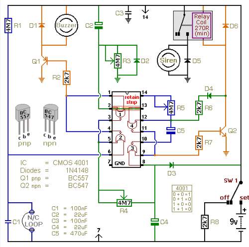
The following circuit illustrates a battery-powered burglar alarm sensor circuit. Features include foil tape and passive infrared sensors (PIRs), as well as magnetic reed contacts. This battery-powered burglar alarm sensor circuit is designed to provide an effective security solution for...
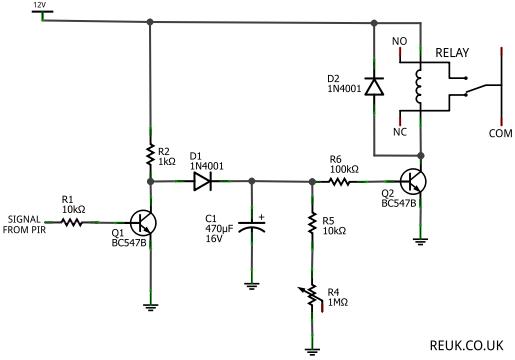
The focus is on 12 Volt DC powered PIR sensors and their associated circuits, which can be directly powered by a 12 Volt battery charged through renewable energy sources such as wind or solar. This article examines how the...
The Thermistor, or NTC (Negative Temperature Coefficient) of 10K, is a standard type. Most types will work. The one in the diagram is a 10K model made by Fenwal (#197-103LAG-A01). The resistance lowers as the surrounding temperature increases, which...
Light Sensitive Switch is a simple project which operates a relay when the light falling on the LDR goes below a set point. More: Input - 12 V @ 55 mA Relay output - NC-C-NO Onboard preset to set the level Power-On...
The brake pad warning light is designed to illuminate when the front brake pads wear down to approximately 25% of their original thickness. This light is activated by a sensor embedded in the brake pads, which consists of two...