
Restoration of the DuMont Industrial Color Monitor

The motor control chassis described is a complex assembly that integrates various components to manage the operation of a CRT monitor from the late 1940s. The absence of a coaxial input suggests a design that predates modern synchronization techniques, relying instead on the physical characteristics of the CRT and its associated circuitry. The pin-type anode connector indicates a historical design choice, likely impacting the overall performance and compatibility with contemporary components.
The dual flyback transformers serve distinct purposes: the horizontal sweep transformer is responsible for generating the horizontal deflection signals necessary for raster scanning, while the high voltage transformer produces the required voltage for the CRT operation. The specification of parallel 6BG6 tubes in the video amplifier highlights the need for high output power and bandwidth, essential for handling the video signal at 18 MHz.
The power supply's design, featuring two regulated B+ outputs, indicates a robust approach to ensuring stable operation across various components. The ongoing development of schematics, particularly for the video and vertical sweep chassis, emphasizes the meticulous nature of restoring or replicating vintage electronic systems.
The exploration of the horizontal oscillator transformer configuration underscores the challenges faced in sourcing specific components for older technology. The potential modification of the circuit to accommodate a standard transformer reflects the adaptability required in such restoration projects. The relationship between the motor control and the sync signal from the power line suggests a nuanced understanding of synchronization in vintage systems, where the pushbutton control's function remains ambiguous.
Limited connections to the video-vertical sweep chassis indicate a streamlined design, with the 8-pin terminal strip and 3-pin Cinch Jones connector facilitating essential communications between components. The collaboration among enthusiasts, such as Darryl Hock and Cliff Benham, exemplifies the community-driven efforts to restore and replicate historical electronics, ensuring that these devices remain functional and appreciated in modern contexts. The documentation and sharing of photographs from the convention serve to preserve the history and ongoing interest in vintage technology.There is not a coaxial input to the motor control chassis, so I doubt that composite sync was fed to it (cables would be 5 or 6 feet long), which might rule out a sync pulse for the red field. Some other interesting things. The CRT has the pin type anode connector that DuMont used in the late 40s. That means the tube was a 12J or Q probably. There are two flybacks - one for horizontal sweep and one for HV. It will be interesting to see how high the HV is. The video amp uses parallel 6BG6s as ouputs. I guess they needed it to handle 18 mHz The power supply is a monster, with two regulated B+ outputs. I will be posting schematics as I get them done, starting with the video and vertical sweep chassis. Today I finished documenting the 3 chassis and everything fell into place. I am still trying to figure out what kind of horizontal oscillator transformer was in the set. It plugged into an octal socket and I think it was wired like this. I think there were 3 windings on it, and since it will be difficult to find a 3 winding transformer, I will try and modified circut, also shown on that link.
That schematic is very similar to the oscillator used in the HV section of the DuMont Royal Sovereign, which was from the same year as this monitor. I have replaced all the paper and electrolytic capacitors. Everything seems to work - HV is 15 KV. I used a standard horizontal blocking oscillator transformer, and it worked fine at 46 kHz. Since I don`t have a signal source yet I`m not sure how the sync will work. Cliff Benham has the wheel, and is building a replica. He has also volunteered to build a motor control circuit, which will be locked to the power line. Here is the schematic of the CBS slave receiver motor control, which he intends to duplicate: I looked at how the motor control would work if the sync was from the power line.
Since the generator is single pole, the motor would always sync to the same filter segment. So the pushbutton wouldn`t select the filter segment. In that case, what did the pushbutton do Why didn`t they just use a synchronous motor and eliminate the motor control stuff That makes me think that they didn`t use 60 Hz sync. There are only two connections to the video-vertical sweep chassis. One is a 8 pin terminal strip, with all pins in use. The other is a 3 pin Cinch Jones connector that mates with the vertical section of the yoke. I think that the yoke actually plugs into the motor control chassis, where the vertical pulse is obtained, and that there was a cable and 3 pin plug from the motor control chassis to the video-vertical sweep chassis.
Darryl Hock has ordered the parts to make a converter for this standard. His job is much easier now that the vertical doesn`t need to be locked to the power line. Cliff arrived at the museum before the convention to install his motor control chassis and new wheel. Darryl delivered the converter and we were able to get the monitor to work. However, there were still problems with it, and Cliff will rebuild his chassis and bring it back later.
Here are pictures from the Convention. 🔗 External reference
Related Circuits
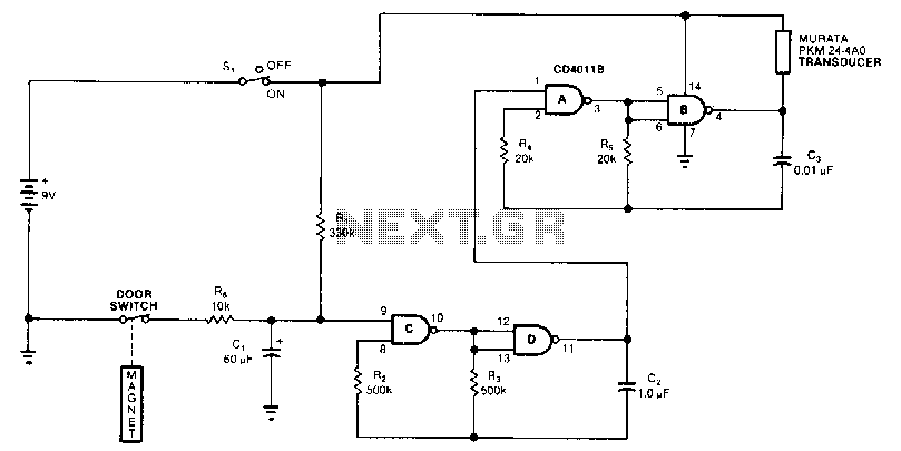
The monitor detects when a door is left ajar and, if the door remains open for more than 20 seconds, it activates a beeping alarm. The circuit utilizes a magnetic reed switch paired with a magnet located on the...
The two optical sensors will provide a count of individuals to the microcontroller, which will relay this value to MCU-II. The microcontroller will detect the entrance of any person through high-to-low pulse transitions on input pins A3 and A4. The...

Works on AVR controllers with RAM and a hardware UART. This code is easily modified to integrate with ROM applications to provide the ability to monitor and interact with ROM applications via a terminal simulation program over an RS-232...
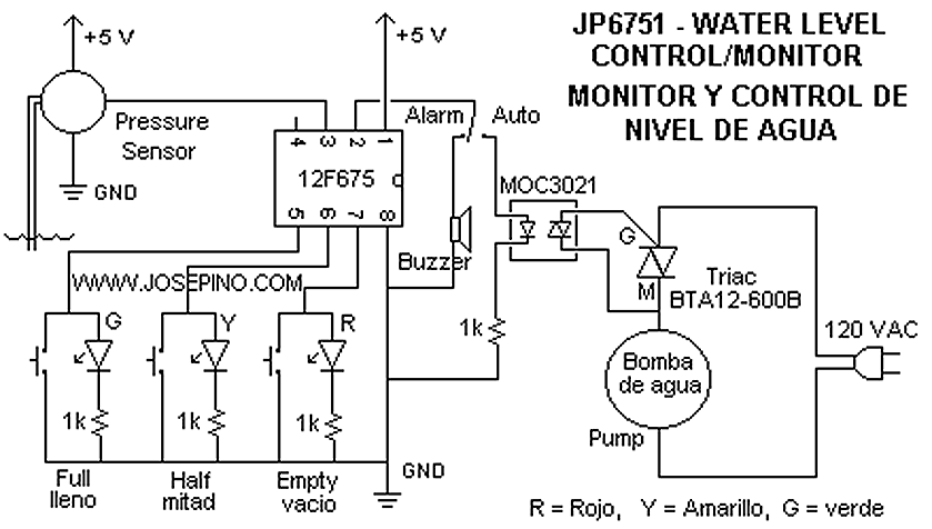
I found some similar circuits but aren't good enough for me. Some circuits measure the water's resistance to determine the level. That is dangerous for drinking water (contamination) or explosive liquids because electricity is in contact with water. The...
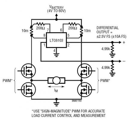
The dual outputs of the LTC6103 can be utilized independently for overload detection or combined as a differential pair to provide a bidirectional signal to an analog-to-digital converter (ADC). A typical circuit for a generic H-bridge application is illustrated....
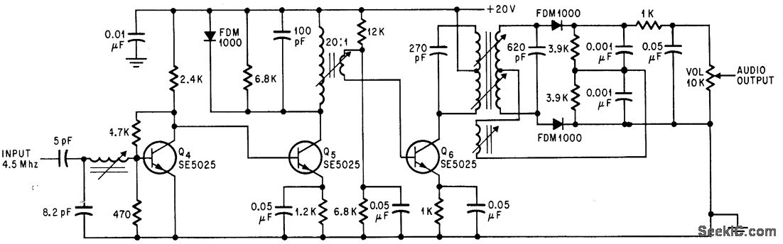
Utilizes three transistor stages and a Foster-Seeley discriminator to produce an audio output of 1 V peak-to-peak. -D. Bray, Solid State Makes Debut in Big Screen Color TV, Electronics, 39:8, p 99-105. The circuit in question employs a combination of...