
I/O monitor program for AVR

The described circuit operates on AVR microcontrollers equipped with RAM and a hardware UART interface. The primary functionality of this system is to facilitate communication with ROM applications through a terminal simulation over an RS-232 interface. This capability is essential for monitoring and interacting with embedded systems in real-time, providing invaluable insights during the development and debugging phases.
The system's architecture allows for the monitoring and manipulation of memory and I/O registers, specifically within the address range of $0000 to $00FF. This range encompasses both the register array and I/O spaces, enabling developers to inspect and modify the state of the microcontroller dynamically. The ability to change values in memory while the controller is operational significantly enhances debugging efficiency, as it allows for immediate feedback on the effects of changes made to the system.
For applications requiring adaptation to microcontrollers with wider stack pointers, it is crucial to ensure proper initialization of both the low (SPL) and high (SPH) byte registers of the stack pointer. The provided assembly code snippets illustrate the initialization process by loading the low and high bytes of the highest RAM address (defined by `ramend`) into the corresponding stack pointer registers. This step is vital for maintaining system stability and ensuring accurate stack operations.
The command set of the monitor allows for comprehensive control over memory operations, including reading and writing data byte-by-byte. This feature is particularly useful for developers aiming to test specific functionalities or to validate the integrity of data stored in the microcontroller's memory and I/O registers. Overall, this setup serves as a robust tool for embedded system development, offering a combination of monitoring, debugging, and interaction capabilities essential for efficient hardware and software integration.Works on AVR controllers with RAM and a hardware UART. This code is easily modified to integrate with ROM applications to provide the ability to monitor and interact with ROM applications via an terminal simulation program over an RS-232 port. It can also be used to stimulate and monitor I/O to aid in debugging hardware. It is very helpful to be able to look around at memory, I/O and peripherals, and change things inside a running controller
If you adapt this to a controller with a stack pointer that is more than 8 bits wide, be sure that both registers in the stack pointer, both spl and sph, are initialized. As an example ldi temp,low(ramend) ;get low byte of highest RAM address for this chip. out spl,temp ;set spl ldi temp,high(ramend) ;get low byte of highest RAM address for this chip.
out sph,temp ;set spl The monitor's commands allow reading, monitoring, and byte-by-byte modification of memory locations $0000 through $00FF, which includes the register array and I/O space. 🔗 External reference
Related Circuits
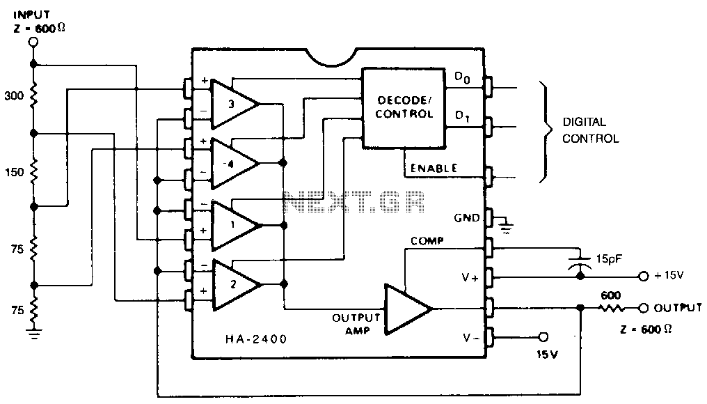
This circuit functions to divide the input signal by a chosen constant (1, 2, 4, 8, etc.). Although T, Z, or L sections could be utilized in the input attenuator, this is unnecessary since the amplifier loading is minimal,...
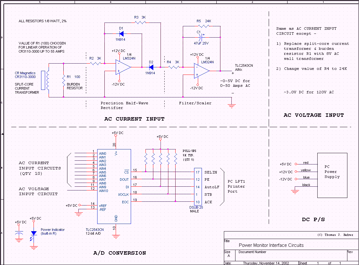
The objective of this project was to monitor power consumption in a residential setting. In addition to tracking total usage, the goal was to separately monitor and compare the usage of major appliances, such as the water heater, heat...
Diode D1 and resistor R1 provide VDD isolation during the programming of 24-pin devices. The jumper J3 must be shorted for 24-pin device programming and left open for 28-pin device programming. The following EEPROMs are pin-compatible with their EPROM...
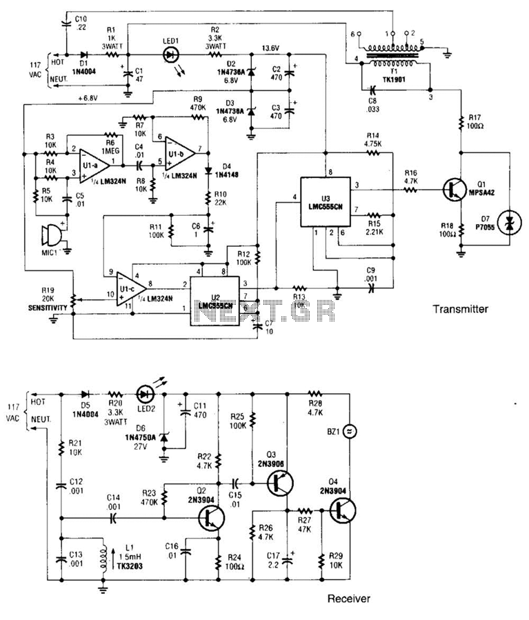
The transmitter operates by deriving its power directly from the AC line. The DC power required for the circuit is generated in two stages: the first stage powers the RF power amplifier, while the second stage supplies power to...
This is a battery tester circuit. This circuit is used to indicate whether the level of a battery voltage is normal, under-voltage, or over-voltage. The battery tester circuit is designed to assess the voltage level of a battery and provide...
The power supply utilizes an Underwriters Laboratory® approved "wall wart" to deliver 24VDC of power, ensuring that the base board does not have any 110V AC or similar voltages present. Power can be supplied through either N1 (on-board) or...