
Resurrecting Tennis for Two a video game from 1958

The schematic for the Tennis for Two replica incorporates an ATmega168 microcontroller at the core of the design, interfacing with two handheld controllers that communicate via a simple wiring scheme. Each controller is designed to be compact, utilizing a 3x2x1 inch plastic project box. The aluminum lid enhances durability and aesthetics. Inside, the 10k potentiometer serves as an adjustable voltage divider, providing an output voltage that varies between 0 to 4.5 V, which is critical for determining the angle of the ball's trajectory. The pushbutton switch is connected to the microcontroller's input pin, enabling the player to trigger the ball toss. This button operates in conjunction with the external pull-up resistor, ensuring that the microcontroller registers a clear high or low signal.
The Cat-5 Ethernet cable simplifies the wiring process, allowing for a neat and organized connection between the controllers and the microcontroller. The use of color-coded wires for power (orange for +4.5 V, green for ground) and signal outputs (brown for the potentiometer and blue for the button) enhances clarity during assembly and troubleshooting. The digital-to-analog converter is integral to translating the digital signals from the microcontroller into analog voltages that can be displayed on the oscilloscope screen, thereby recreating the original game's visual output.
In summary, the Tennis for Two replica leverages modern electronic components to recreate a classic game, utilizing a straightforward design that is accessible to hobbyists. The combination of an ATmega168 microcontroller, custom controllers, and an oscilloscope provides a functional and engaging experience that mirrors the original concept while benefiting from contemporary technology advancements.Tennis for Two presented a tennis court shown from the side on an oscilloscope screen, where handheld controllers allowed the two players to toss the ball to each other. Each controller had two controls: a button and a knob. With the button, you could hit the ball at any time of your choosing when it was on your side of the net, and with the knob you could choose the angle at which the ball was hit.
The game was based on the best contemporary technology: analog electronic computers built out of op-amps, relays, and the occasional transistor. It took Higinbotham and his technicians several weeks to design and build the game. Of course, some things have changed over the last 50 years. Using convenient modern electronics, we have designed a functional and playable replica of the original that can be put together by a hobbyist in a couple of evenings.
You can watch the video of our recreation on YouTube or embedded here: So, the next question you might ask is, How do you build this And, if that is in fact what you`re asking right now, you`re in the right place. The quick answer is, with an oscilloscope, an AVR microcontroller, and a digital to analog converter.
Ready to get going Before we start, let`s be clear that this is not a tutorial in how to build an oscilloscope. Tennis for Two is supposed to display on a scope, so beg, borrow, or buy one if you don`t have one handy.
Older low-end analog scopes like mine (a Hameg!) usually go for $50-$150, and if nothing else, you can always make a Scope Clock out of it later. There are three parts to the electronics that we`re building. First, there is the AVR microcontroller the brains of the outfit. The specific variety that we`re using is the ATmega168, the same chip used in (for example) the Arduino platform.
Secondly, there are two handheld controllers that connect to the ATmega168 microcontroller. Each handheld controller has a knob and a button. Third, there is the digital to analog converter that takes the output from the AVR and uses it to drive the scope. There two controllers are identical little project boxes that each have the button and knob, as well as a cable going back to the other electronics.
The controllers themselves are built from 3x2x1 ³ plastic project boxes with aluminum lids, e. g. , Philmore #PB140 or Radio Shack #270-1801. Let`s take a peek inside. Inside each controller we have a 10k single-turn pot (Jameco #286206) and pushbutton (Jameco #26623). The knob on the pot is a fancy machined aluminum type for extra snazz. (Jameco #138482). The pot is used to vary an output voltage (that controls the firing angle) between 0 and 4. 5 V, and the button, when pressed, pulls one of the inputs from 4. 5 V down to 0V. (We use an external 10k pull-up on the pin to make that happen. ) The circuit diagram for one of the controllers looks like this: To simplify the wiring, we used some old Cat-5 (ethernet) cable as the cables for the controllers.
Inside Cat-5 cable are four color-coded twisted pairs: orange, green, blue, brown. For each of these, we stripped and twisted the two conductors together to make four effective (but thicker) color-coded wires. We used orange (+4. 5 V) and green (ground) for power, and the other two for signals: brown for the analog knob output and blue for the button switch output.
To use an AVR microcontroller, we need to provide it with power and ground usually 3-5 V and we also need to be able to hook it up to a programmer (at least once). How do do that is described in this article about minimal target boards for AVR microcontrollers. 🔗 External reference
Related Circuits
The designer requires a 1-Wire host computer IO framework that operates at 1.8V. Most 1-Wire devices are unable to function at this voltage. This application recommends implementing a 1.8V 1-Wire host computer alongside a 5V 1-Wire reference design for...
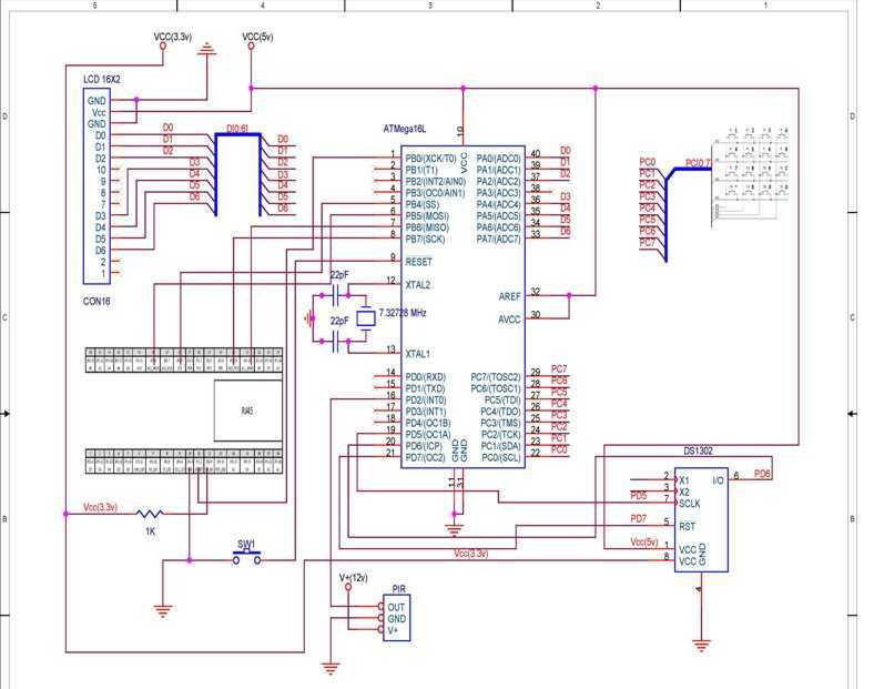
TCP based security system using the Ethernet module offered within the contest, an ATmega16L microcontroller, a PIR as a sensor and few other peripheral devices, which is specially targeted for homes and small business owners. I have used through...
Should I cut the blue wire... or the red...? This is a very common phrase in many movies when the action hero has a bomb in front of him with little time left and he has to choose which...
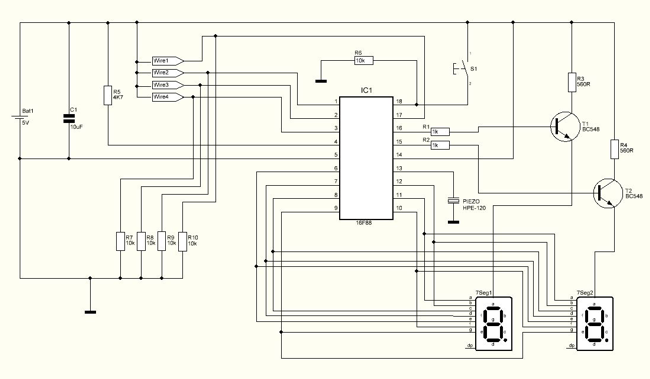
The Hand Steadiness Tester is a game which tests the steadiness of your hand. The player has to take the ring from one end to another end without touching it to the wire. In this the player gets 4...
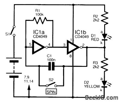
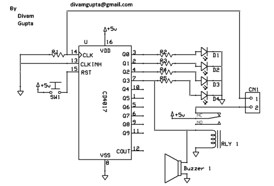
This circuit is designed to electronically simulate the tossing of a coin using a 4049 hex inverter integrated circuit (IC). It employs two of these ICs, specifically IC1a and IC1b, which are configured as an astable oscillator. This configuration...
Video-DVM is a very cheap DVM that shows how an output as complex as a videocomposite signal can be generated entirely in software: two I/O pins and three resistors are all the hardware required. Connected to any TV set...