
Video DVM circuit

The Video-DVM circuit utilizes the Atmel AT90S1200 microcontroller, which is characterized by its 512 words of flash memory, 32 bytes of RAM, and 64 bytes of EEPROM, making it suitable for a variety of applications. The microcontroller's Harvard RISC architecture allows for efficient instruction execution, enabling complex tasks to be performed with minimal instruction cycles. The circuit design incorporates a simple two-bit asymmetrical digital-to-analog converter (DAC), constructed from three resistors, which generates a composite video signal at a standard voltage level of 1 Vpp. This output is compatible with most television sets equipped with SCART or AV inputs.
The device's functionality extends beyond a basic digital voltmeter (DVM) and can be adapted for multiple applications, including frequency measurement, game scorekeeping, irrigation timing, video pattern generation, and weight measurement. The software is designed to be interrupt-driven and time-balanced, allowing for real-time data display on the TV set. The display features both large digit readouts and an analog bar display, enhancing user interaction.
For data logging purposes, the Video-DVM includes a serial data output that transmits ASCII data at a baud rate of 1200, utilizing standard TTL levels, which are compatible with most personal computers. This eliminates the need for additional voltage level translation, although an external MAX232 can be added if required.
Input functionality is enhanced with internal pull-up resistors on all input pins, which facilitate easy connection of external components such as buttons and switches. A "max-min clear" button and a three-position dip switch for decimal point selection are directly interfaced with the microcontroller pins. Additionally, an LED indicator is included to signal the completion of each measurement, providing visual feedback to the user.
Overall, the Video-DVM circuit serves as both a practical measurement tool and a versatile platform for educational and hobbyist applications, demonstrating the capabilities of software-driven electronics in generating complex output signals.Video-DVM is a very cheap DVM that shows how an output as complex as a videocomposite signal can be generated entirely in software: two I/O pins and three resistors are all the hardware required. Connected to any TV set it displays voltages, included max and min peaks, using both giant digits and an analog bar-display .
A serial data output for computer data logging is provided, too. The micro is the Atmel’s AT90S1200, ideally suited for hobbysts thanks to its 512 words flash memory, public programming protocols, free assembler and simulator available at www.atmel.com. More recently, other tools as free Basic and C compilers appeared on the Internet. The circuit is not only a working project but also a guideline for any application using a tv set as giant display: all the hard work (interrupt driven, time balanced display software) is ready made, letting even novices to modify the code to build anything ranging: from a multimeter... to a frequency meter.... to a game scoreboard.... to a watering timer.... to a video pattern generator.... to a weight scale.... The detailed flash programming protocol is available on the web site, too. The chip has 32 bytes of RAM, 64 byte of EEPROM, 512 words of program memory, and an 8 bit timer. The instruction set is coincise and very well balanced, and thanks to an Harward RISC architecture even a complex task as the one described here is accomplished using only about 400 instructions.
The instruction cycle time is very short, letting software video synthesis possible. A simple two bits, asymmetrical DAC built around three resistors feeds the composite video signal at a standard level of 1 Vpp suitable to be input to any TV set with a SCART connector or an AV (VCR) input. Even the serial datastream (ASCII data at 1200 baud, no parity, 8 data bits, 1 stop bit) is generated by software.
The level is TTL: most personal computers work with TTL levels as well as with standard RS232 levels, provided that the connecting cable is not too long, so I found a voltage translator like the MAX232 not necessary. If you want, you can add it externally; in that case you must invert the polarity inverting the "set bit" and "clear bit" instructions in code (the position is clearly annotated on the listing).
All input pins have internal pullups and high current sink, so the max-min clear” button and the three decimal point selection dipswitch or jumpers are connected directly between the pins and ground. A led, flashing each time a measurement is completed, is connected to an output pin. The voltage is read using a 10 bit serial ADC converter. 🔗 External reference
Related Circuits
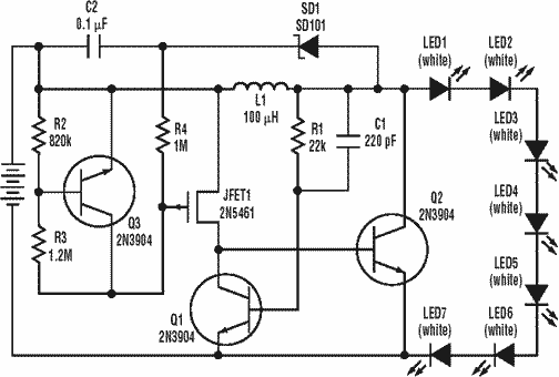
A low power, long-life LED flashlight circuit. Electronic Design proposed a simple circuit to resolve this in a recent article. The front end of their circuit draws less than a milliamp of extra current. The described LED flashlight circuit is...
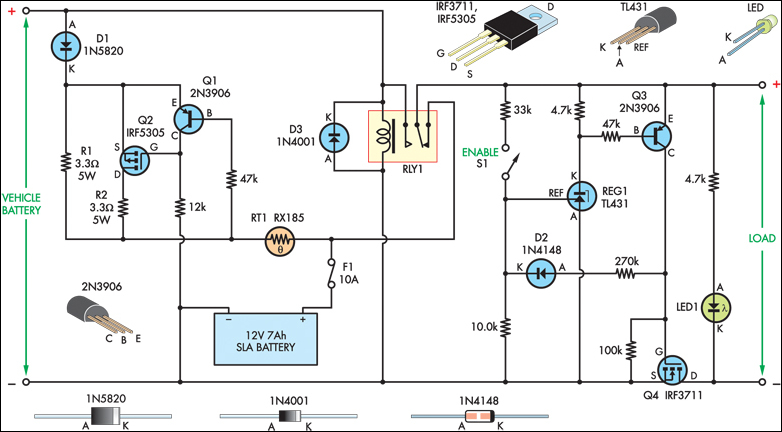
The SLA battery is charged from the vehicle's battery. When the engine is running, the voltage remains fairly constant, which greatly simplifies the charging circuit. If the SLA battery is fully charged, any further charging current from the vehicle...
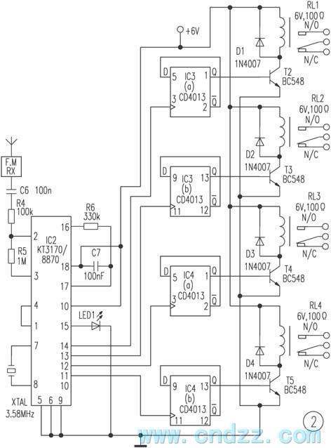
The remote control transmitter consists of a DTMF generator and an FM transmitter circuit. A UM91214B phone-specific integrated circuit (IC) is utilized to generate the DTMF signal, with a 3V power supply provided by a 3V zener diode (D1)....
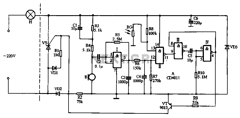
The circuit utilizes CD4011 digital circuits to create a sound-activated light lamp with a dual-control delay section. The left portion of the circuit represents the lighting lines, while the right part consists of the sound and light control delay...
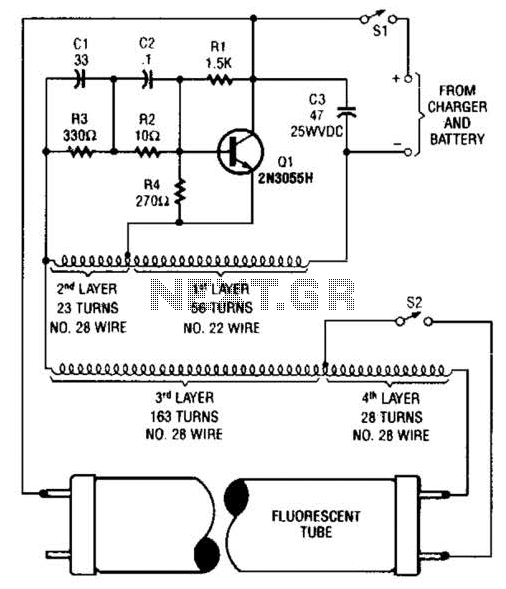
A 2N3055 oscillator (Q1) drives a homemade transformer, wound on a Vk ferrite rod. S2 is used as a filament switch and can be eliminated if desired. A 20-W fluorescent tube is recommended. The supply voltage is 12 V. The...

The circuit consists of an oscillator, a counter, and an Iseki circuit divided into three parts. The oscillator is based on the NE555 timer and several external RC components, generating a pulse signal for the counter. The instantaneous power...