
Reverse Engineering an Electric Fence Charger
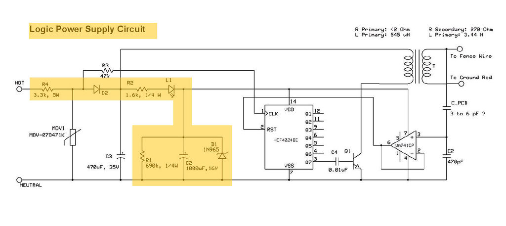
The product features a logic circuit that is integral to managing the timing of output pulses. This circuit typically consists of various logic gates, such as AND, OR, and NOT gates, which work together to create specific timing sequences. The timing control is essential for applications that require precise synchronization between multiple signals or events.
The circuit may employ a combination of flip-flops and counters to generate the desired pulse widths and intervals. For instance, a monostable multivibrator can be used to produce a single output pulse of a defined duration in response to an input trigger. Additionally, a timer IC, such as the 555 timer, could be implemented to achieve more complex timing functions, allowing for adjustable pulse lengths and delays.
The output pulses generated by this logic circuitry can be used to drive various loads or trigger other circuits, making it versatile for a range of applications, including digital communication, signal processing, and control systems. The design considerations for this circuit include ensuring that the timing is accurate and stable, which may involve the use of capacitors and resistors to filter noise and prevent unintended signal fluctuations.
Overall, the logic circuitry serves as a crucial component in managing the timing of output pulses, facilitating effective operation in the intended electronic applications.This product includes some logic circuitry used to control the timing of the output pulses, which will be discussed in a later step. The logic circui.. 🔗 External reference
Related Circuits
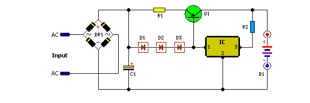
The following circuit illustrates a portable NiCd battery charger circuit diagram. The portable battery charger is designed to facilitate the charging of nickel-cadmium batteries. The portable NiCd battery charger circuit typically consists of several key components, including a transformer, rectifier,...
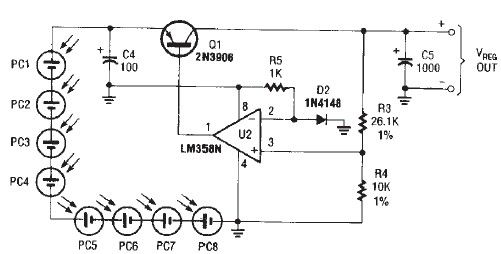
The circuit diagram illustrates a portable solar charger that utilizes an LM358N operational amplifier and a single transistor. This regulator delivers a constant output of 2.4 volts DC, suitable for powering small devices requiring energy from two AA battery...
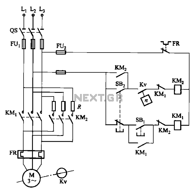
The circuit depicted in Figure 3-124 operates without an intermediate relay. Kv serves as the speed relay, activating when the electric motor speed exceeds 120 r/min while the contact is closed. If the speed drops below 100 r/min, the...
Unlike many units, this battery charger continuously charges at maximum current, tapering off only near full battery voltage. In this unit, the full load. This battery charger is designed to operate with a continuous charging mechanism, maintaining the maximum current...
The above circuit is a precision voltage source and contains a temperature sensor with a negative temperature coefficient. Meaning, whenever the surrounding or battery temperature increases, the voltage will automatically decrease. The temperature coefficient for this circuit is -8mV...
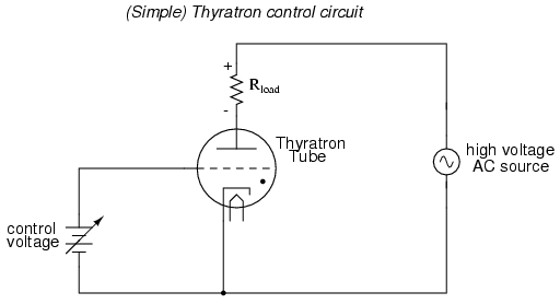
An often neglected area of study in modern electronics is that of tubes, more precisely known as vacuum tubes or electron tubes. Almost completely overshadowed by semiconductor, or "solid-state" components in most modern applications, tube technology once dominated electronic...