
Portable solar charger designed using LM358N

The portable solar charger circuit is designed to efficiently convert solar energy into a usable electrical output for small electronic devices. The core components include the LM358N operational amplifier, which is configured to maintain a stable output voltage of 2.4 volts. This is critical for devices with specific voltage requirements, ensuring reliable operation without damage due to overvoltage.
The inclusion of a transistor serves as a switching element, allowing for control of the current flow from the solar cells to the load. The transistor must be selected based on the expected load current, which, in this case, is capped at 125mA. This current rating is sufficient for devices like portable radios or small LED lights, making the circuit versatile for various applications.
The low dropout voltage of 0.3 volts is particularly advantageous, as it allows the circuit to operate effectively even when the solar cell output is slightly below the required voltage. This characteristic is crucial for maintaining performance during varying sunlight conditions, ensuring that the charger can still function effectively when solar intensity fluctuates.
When selecting solar cells for this application, it is important to consider their voltage and current output characteristics. The solar cells should be capable of providing sufficient voltage to overcome the regulator's dropout voltage while also delivering enough current to meet the load requirements. Typically, a solar panel rated around 5V with sufficient current capacity would be appropriate for this circuit.
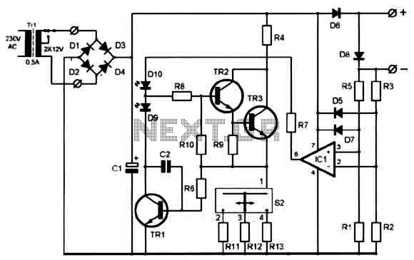
Overall, this portable solar charger circuit presents a practical solution for harnessing solar energy for small electronic devices, combining efficiency with simplicity. Proper component selection and circuit design ensure that it operates effectively in real-world conditions, making it a valuable addition to portable power solutions.As you can see in circuit diagram, this portable solar charger circuit, is based on a LM358N operational amplifier and one transistor. This regulator provide a constant 2. 4 volts DC and can be used for powering small devices that needs to be powered from two AA battery cells.
Because the regulator has a low drop down voltage of 0. 3 volt you sho uld take care about this when you choose solar cells. Maximum load current for this solar charger electronic circuit project is around 125mA typically, enough for small portable devices like radios. 🔗 External reference
Related Circuits
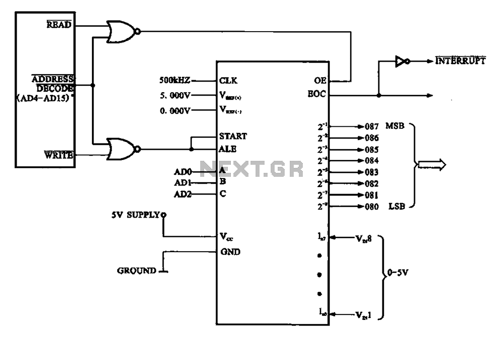
An A/D conversion circuit is designed to convert analog voltage into a digital signal encoding circuit. It utilizes ADC0808/ADC0809 circuit chips, which can convert analog signals into an 8-bit digital output signal. The A/D conversion circuit employs the ADC0808 or...
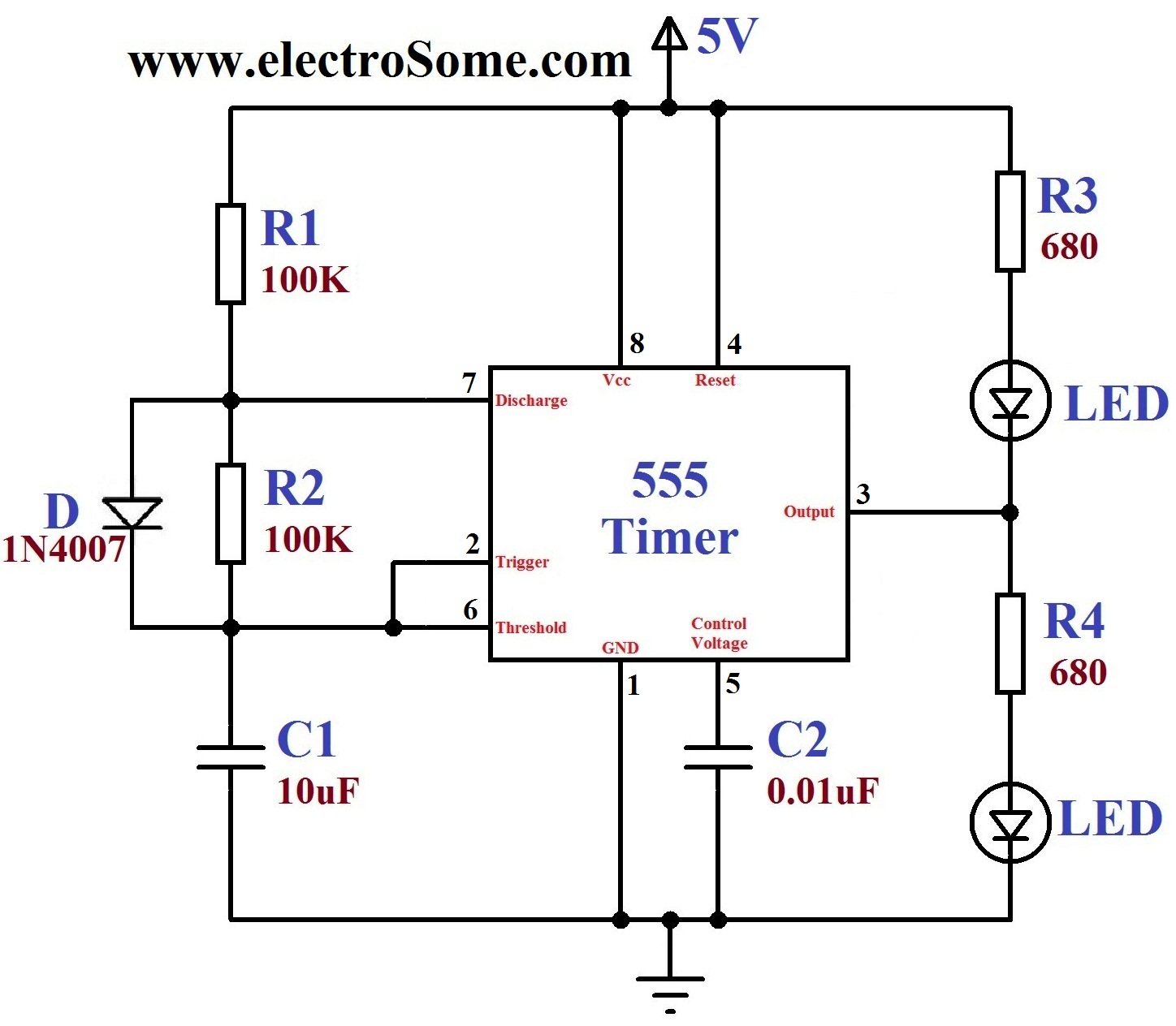
A dancing light can be easily constructed using a 555 timer wired in astable mode. This circuit alternately blinks two LEDs with a certain delay and can be modified to include additional LEDs or to control incandescent lamps. The...
The BFP640 transistor is utilized for 1575 MHz Global Positioning Satellite (GPS) applications, specifically as a Low Noise Amplifier (LNA). The design objectives include a minimum gain of 16 dB, a noise figure of less than 0.6 dB, an...
This portable solar lantern circuit utilizes a 6 volt/5 watt solar panel, which is widely available. With this photovoltaic panel, an economical, simple, yet efficient and truly portable solar lantern unit can be constructed. The next essential component required...
A clever charger circuit that safely charges any Ni-Cd battery. It offers charge current selection, polarization detection, protection, and the ability to connect multiple batteries in series. Ni-Cd batteries can be recharged more than 1000 times before becoming unusable....
The voltage to frequency converter (V/FC - VCO) circuit consists of a UJT (uni-junction transistor) oscillator in which the timing charge capacitor C2 is utilized. The voltage to frequency converter circuit operates by converting an input voltage into an output...