
Simple Op Amp Audio Amplifier
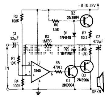
The circuit employs a CA3140 operational amplifier, which is known for its high input impedance and low output impedance, making it suitable for driving power transistors in audio applications. The complementary output stage utilizing Q1, Q2, and Q3 typically consists of NPN and PNP transistors configured to provide push-pull operation. This configuration enhances efficiency and allows for greater output power while minimizing distortion.
The output power capability of this circuit is contingent upon several factors, including the supply voltage, which in this case is specified at 30 volts, and the load impedance of the speaker connected to the output. Higher impedance speakers allow for greater power output, reaching up to 2 watts under ideal conditions.
Thermal management is critical in this design, as the power dissipation in transistors Q2 and Q3 must be carefully monitored to prevent overheating. Adequate heatsinking may be required to maintain safe operating temperatures, especially at higher output levels. The circuit may also include biasing resistors to set the quiescent current of the output stage, ensuring linear operation and minimizing crossover distortion.
Overall, this configuration is well-suited for audio amplification applications, providing a robust solution for driving speakers with sufficient power while maintaining sound quality. Proper attention to component selection and thermal management will enhance the reliability and performance of the circuit. A CA3140 drives a complementary output stage Ql, Q2, and Q3. Output power depends on supply voltage and limit s on dissipations of Q2 and Q3, but it can be 1 or 2 W with a higher impedance speaker and a 30-V supply. 🔗 External reference
Related Circuits
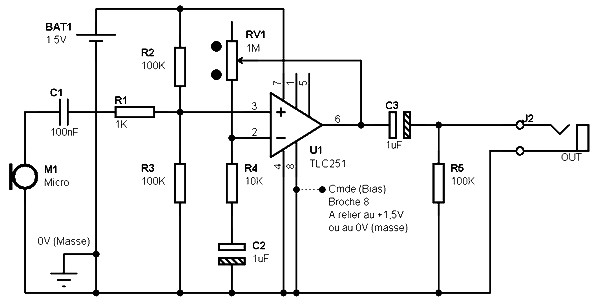
The schematic for a microphone preamplifier utilizes the TLC251, a programmable low-power operational amplifier. A control input, referred to as BIAS (pin 8), determines the operational mode of the amplifier. When this pin is connected to the positive potential...
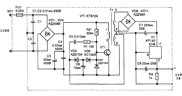
The pulse transformer T1 utilizes a ferrite core, specifically M2500NMS-2 or M2000NM9, with dimensions of Sh5h5 (cross-section of the magnetic coils at 5G—5 mm with a center gap). The winding wire is of type PEL-2. The primary winding consists...
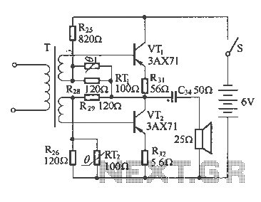
The following diagram illustrates a common output transformerless (OTL) amplifier circuit that delivers an output power of 100 mW. The circuit includes an output transformer and a capacitor, which work in conjunction with speaker units. The frequency characteristics of...

The amplifier utilizes a single MRF245 transistor and delivers 80 W of output power with a gain of 9.4 dB across the frequency range of 143 to 156 MHz. The circuit design for the amplifier featuring the MRF245 transistor is...
Dynamic microphones utilize a moving coil within a magnetic field to convert mechanical movements into electrical signals. An ordinary mini speaker can be transformed into a... Dynamic microphones operate on the principle of electromagnetic induction. When sound waves hit the diaphragm...
This is a single-ended triode amplifier built using the 813 transmitting pentode, configured as a triode. It is a powerful single-ended amplifier that operates effectively. A single pentode, the 12HG7 video amplifier tube, serves as the driver, while a...