
RF detector circuit diagram using transistors

This RF signal detection circuit is designed to operate over a wide frequency range, specifically from below the standard broadcast band up to 500 MHz. The circuit utilizes a combination of transistors to amplify the incoming RF signals, allowing for effective detection of both weak and strong signals. The visual indication is provided by an LED, which lights up when an RF signal is detected, while an audible indication can be achieved through a connected speaker or buzzer.
The circuit's sensitivity can be fine-tuned using a potentiometer (R2), which adjusts the bias of diode D2. This flexibility enables the user to optimize the detection capability according to the specific application or environment. A critical consideration in the circuit design is minimizing stray inductance, which can adversely affect performance. Therefore, it is recommended to keep the leads of the diode and capacitor (C1) as short as possible.
For the transistors, various high-gain options are available. For the PNP transistor (Q2), suitable choices include the 2N3906 or 2N2907. For the NPN transistor (Q1), options such as the PN2222A or 2N3904 are recommended. The selection of these components will influence the overall gain and performance of the circuit, making it essential to choose transistors that meet the required specifications for the intended application.
Overall, this circuit serves as a versatile solution for RF signal detection, providing both visual and audible feedback while allowing for sensitivity adjustments to cater to various detection scenarios.This circuit responds to RF signals bellow the standard broadcast band to over 500MHz and provides an visual, and audible indication when the rf signal is detected. By adjusting the bias of D2 with the R2 potentiometer the circuit can detect low power or strong signals.
A very sensitive setting can be obtained by modifying R2 until the LED begins
to light. Keep diode and capacitor (C1) leads short to minimize stray inductance. The used transistors can be: 2N3906, 2N2907 or other PNP high gain transistor for Q2 and PN2222A, 2N3904 or other NPN high gain transistor for Q1.
🔗 External referenceRelated Circuits

This presence detector or proximity sensor circuit responds to the presence of any conductive object, including humans. The sensitivity can be adjusted with potentiometer P1, which is positioned at a considerable distance from the rest of the circuit. This...
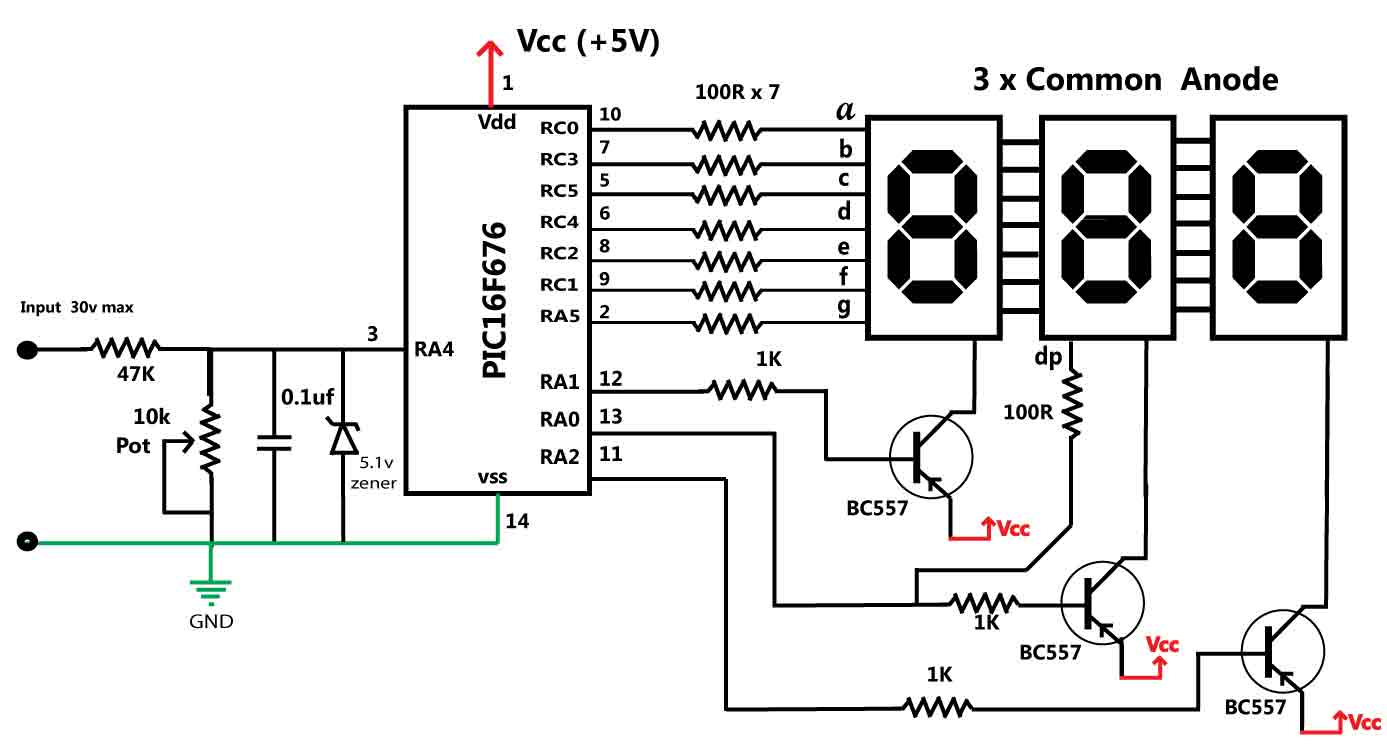
This is a simple application of the internal 10-bit ADC (analog-to-digital converter) of the PIC16F676 microcontroller. This circuit can be used to measure up to 30 V DC. Possible applications include a benchtop power supply or as a panel...

This circuit indicates that a power outage occurred for 1, 10, 100, and 500 seconds based on the values provided for R* and C*. After a power failure, the circuit can be reset by pressing the Reset button. The described...

Quasi square wave resonant converters, also referred to as quasi resonant (QR) converters, facilitate the design of flyback Switch Mode Power Supplies (SMPS) with diminished Electro Magnetic Interference (EMI) and enhanced efficiency. Due to their low noise generation, QR...
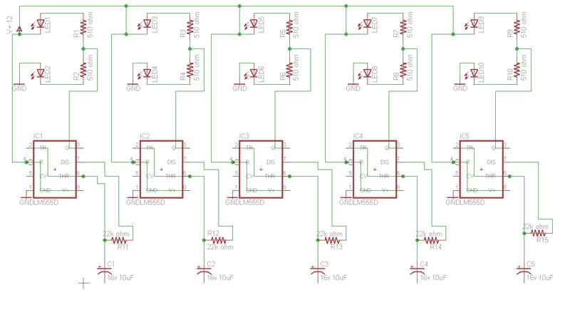
Build a circuit that will flash five pairs of LEDs at variable rates. To achieve this, a circuit utilizing five NE555 timers has been designed. Trim pots will be used to control the variable flash rate. Assistance is needed...
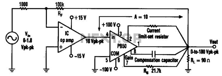
An Apex PB50 Booster Amplifier, along with an integrated circuit (IC) operational amplifier, can be utilized in a high-voltage operational amplifier configuration to convert a small analog signal into a 180-V peak-to-peak signal. Apex Microtechnology produces a variety of...