
30 volts panel volt meter using pic mcu

The circuit described utilizes the internal 10-bit ADC of the PIC16F676 microcontroller, which is capable of converting an analog voltage signal into a digital representation. The primary function of this circuit is to measure DC voltage levels up to 30V, making it suitable for various applications such as power supply testing or as a digital panel meter in different electronic systems.
The voltage measurement is accomplished using a resistor network configured as a voltage divider. This network comprises a 47kΩ resistor and a 10kΩ trim potentiometer, which are selected to ensure that the maximum input voltage is scaled down to the ADC's reference voltage of 5V. The voltage divider configuration allows for the calculation of the output voltage (Vout) as:
\[ V_{out} = V_{in} \times \frac{R2}{R1 + R2} \]
Where R1 is the 47kΩ resistor and R2 is the 10kΩ potentiometer. This design ensures that at a maximum input of 30V, the output voltage presented to the ADC remains within the safe operating range.
The circuit employs a three-digit common anode 7-segment display for visual output of the measured voltage. Each segment of the display is multiplexed, meaning that only one display is activated at any given time while the others are turned off. This technique reduces the number of required microcontroller pins and simplifies the driving circuit. The multiplexing process is managed by the microcontroller, which cycles through each display rapidly enough that the human eye perceives all three digits as being lit simultaneously.
For further insights into the multiplexing technique and its implementation, reference can be made to Microchip's application note AN557, which provides additional information on driving multiplexed displays with PIC microcontrollers. This note serves as a valuable resource for understanding the intricacies involved in managing multiple outputs from a single microcontroller efficiently.
In summary, this circuit effectively demonstrates the application of the PIC16F676 microcontroller's ADC capabilities, offering a practical solution for voltage measurement in a compact and efficient design. The use of a voltage divider ensures compatibility with the ADC's input range, while the multiplexed display provides a clear visual representation of the measured values.This is a simple application of internal 10-bit ADC(analogto digital converter) of PIC16F676 microcontroller. you can use this circuit to measure up to 30 v dc. the possible applications are on bench top power supply or as a panel meter invarioussystem. MICROCHIP`S PIC16F676 is the heart and brain of this circuit. the internal adc of the mcu with a resistor network voltage divider is used to measure the input voltage. then 3 digest of comm anode 7 segment display is used to display finalconverted voltage. as you can see in the schematic the displays are multiplexed with each other. means we switch on one display and put the corresponding digit on this while other two displays are off this cycle go for each of thedisplay. you can find more about driving multiplexed 7 segment led display from a pic mcu in application note from microchip AN557Four Channel Digital Voltmeter with Display and Keyboard as you can seen in the schematic the 47k resistor and 10 ktrim pot is connected ias a voltage divider configuration.
we all know very well that by default pic micro controller ADCreferencevoltage is set to vcc(+5v in this case). sowhatwe have to do is make such voltage divider that can divide out maximum range 30 volts to 5 volts.
so we need is Vin/6 => 30/6 =5v voltagedivider. and to keep as less as possible attenuation on the under test voltage we have to keep the voltagedivider resistor value in fewthousand ohms because it takes very little current from the target but asmuch to drive adc of pic. 🔗 External reference
Related Circuits
This constant current constant voltage switched-mode power supply (SMPS) is designed for efficient battery charging. The circuit outputs a constant voltage of 7.2V and a constant current of 600mA. The operation mechanism is straightforward: when the load impedance is...
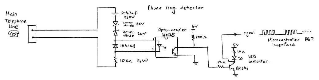
This circuit detects the dial tone from a telephone line and decodes the keypad pressed on the remote telephone. The dial tone heard when picking up the phone is referred to as Dual Tone Multi-Frequency (DTMF). This name originates...
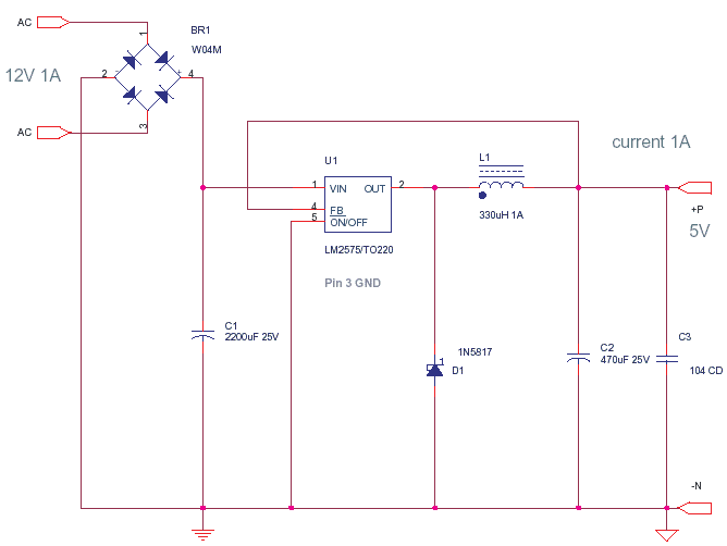
A power transistor with a voltage drop of 4 volts and a current of 3 amps may dissipate approximately 12 watts of heat, presenting a challenge in series regulators. In contrast, a saturated transistor or MOSFET with a voltage...
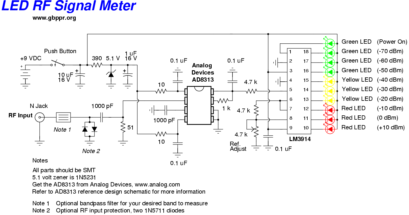
This RF Wave Absorption meter detects signals from 10 centimeters to 10 meters, depending on the setting of the 22 MegOhm gain adjustment potentiometer and the transmitter power. The RF signal is captured through germanium OA91 diodes and rectified...
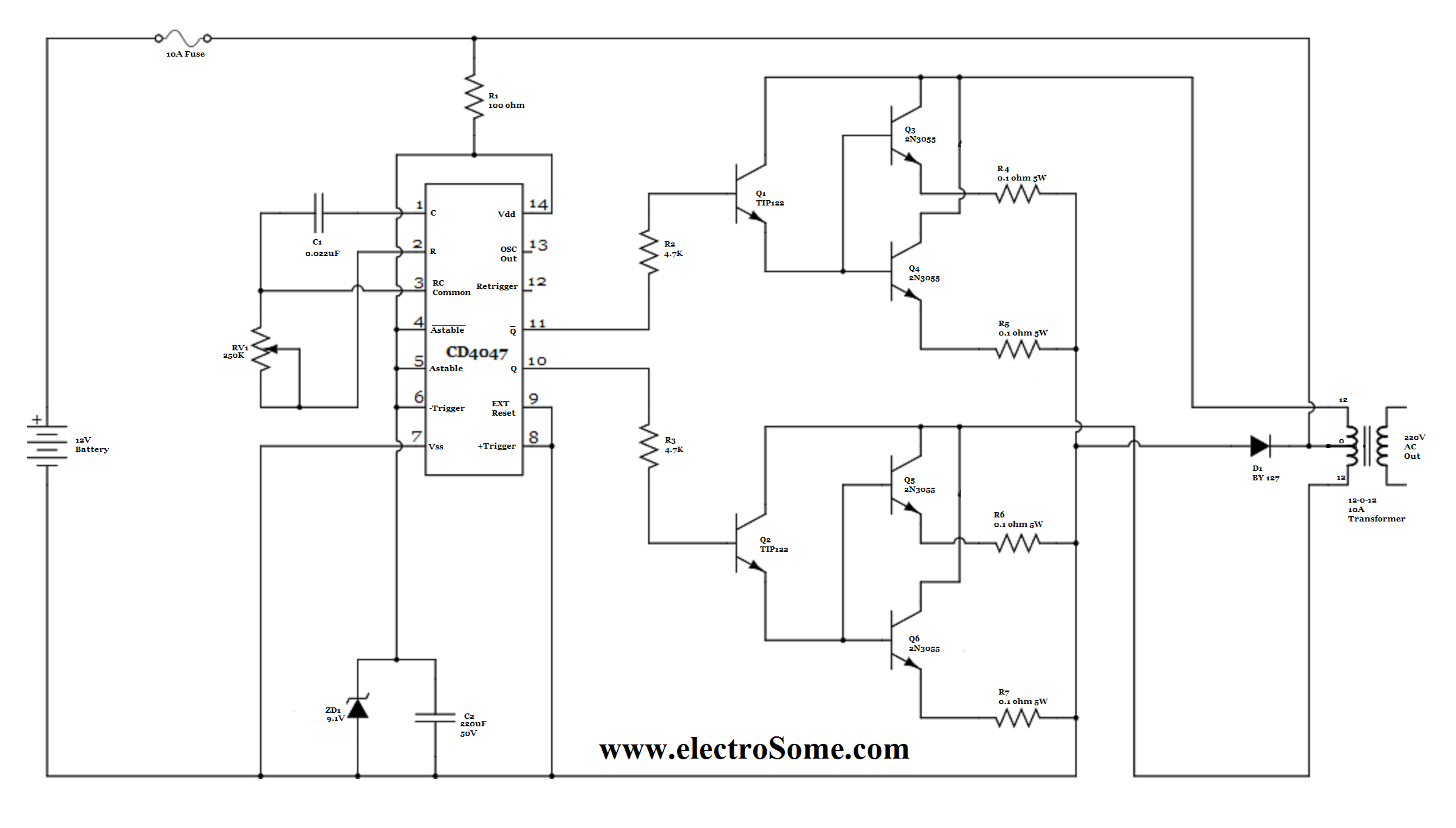
For basic requirements, square wave inverters can be utilized as they are simple, low-cost, and easy to construct. However, pure sine wave inverters are preferred for driving inductive loads. This document discusses a simple low-power square wave inverter using...
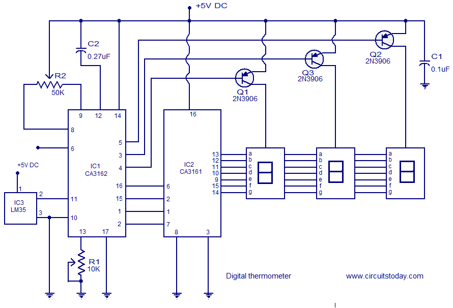
A simple digital thermometer circuit without a microcontroller and featuring a seven-segment LED readout is presented. The circuit utilizes three integrated circuits (ICs): CA3162, CA3161, and LM35. The CA3162 is a monolithic analog-to-digital (A/D) converter with a BCD output....