
RF Field Strength meter

The circuit is powered by a single 1.5 volt AA cell. The current drain is so small, about 60 microamps, I didn't bother with an on-off switch - I just slip a battery in for the day and hope I remember to remove it when I'm done. The supply voltage can be increased up to the breakdown voltage of the transistors to increase the sensitivity, but beware - the sensitivity to thermal drift will increase as well.
How it works: RF voltage coupled by the antenna is applied to the base of one transistor, and this current causes an increase in collector current of the transistor (the transistor on the far-right of the schematic), increasing the voltage drop across the 39k resistor on its collector, which results in a reduction of the collector voltage. That resistor, along with the capacitor from the collector to ground makes a 1 kHz low pass filter. The transistor in the middle provides a reference voltage for the voltmeter. With no RF field applied, the 10K pot is used to make the voltages on the two collectors equal, making zero volts across the voltmeter's terminals. If you are the kind of person who likes to see the meter read zero when there is no signal present, it is suggested to use a 10k pot with a knob instead of a trimpot, or better yet, build the auto zero version.
The described circuit functions as a broad-band RF field strength indicator, utilizing a simple transistor-based design to detect radio frequency signals across a wide range of frequencies. The main components include a small antenna, typically a 15 cm length of insulated wire, which captures RF energy and feeds it into the base of a transistor. The choice of transistors is flexible, with options such as the 2N2222 or MPSH34, the latter being preferred for its low input capacitance, which enhances sensitivity in VHF and UHF applications.
The circuit operates on a single 1.5V AA battery, achieving a minimal current drain of approximately 60 microamps, allowing for prolonged usage without frequent battery replacement. The absence of an on-off switch simplifies the design, although users are advised to remove the battery when not in use to prevent depletion.
The RF signal induces a variation in collector current within the transistor, which in turn alters the voltage across a 39k ohm collector resistor. This voltage drop is critical, as it forms part of a low-pass filter configuration when combined with a capacitor connected to ground, effectively filtering out high-frequency noise and allowing only the desired signal to pass through.
A second transistor in the circuit serves as a reference for the digital voltmeter (DVM), ensuring accurate readings. The inclusion of a 10k potentiometer allows for offset adjustments, enabling the user to calibrate the circuit such that the voltmeter reads zero in the absence of an RF signal. This feature is particularly useful for those who prefer a clean baseline reading.
In summary, this RF field strength indicator circuit is a practical, low-cost solution for measuring RF signals across a broad frequency range, with careful consideration given to component selection and circuit design to optimize performance and ease of use.As I used this probe last nigh to determine if a 384 MHz oscillator was really working or not, I remembered email I received a while ago, asking how to make a field strength indicator without the microcontroller. Thus this page. If you want the auto zero version, which is this circuit with an auto-zero integrated circuit, use the circuit shown on this page for details.
This broad band probe has a small antenna (about a 15 cm length of insulated wire). Radio Frequency energy coupled to the antenna is detected and made available to drive millivolt level signals to the input of a DVM (Digital Volt Meter). Its battery powered for convenience with very low current drain and automatic shutdown for long battery life.
You can use 2N2222's for the transistors if you want. The MPSH34 has two things going for it: low input capacitance, and I have a lot of them on hand. I've used the circuit shown below to check the output of transmitters at 4 MHz, 35 MHz, 55 MHz, 100 MHz, 384 MHz, 900 MHz, a cell phone, and a microwave oven. It really is broad band, and I am sure the response varies considerable with frequency. Since the collectors and emitters of the detector transistor are both at RF ground, choice of transistors isn't all that critical.
A low base-collector capacitance will enhance the VHF and UHF sensitivity. All transistors should be of the same type and thermallly coupled to one-another to minimize thermal drift. The DC gain of the detector is about 25X (estimated by multiplying the voltage drop across the collector load by 38).
Assembly is not critical and mine was built on punched fiberglass board without a ground plane. The 10k pot is a the offset adjustment. The circuit is powerd by a single 1.5 volt AA cell. The current drain is so small, about 60 microamps, I didn't bother with an on-off switch -I just slip a battery in for the day, and hope I remember to remove it when I'm done. The supply voltage can be increased up to the breakdown voltage of the transistors to increase the sensitivity, but beware - the sensitivty to thermal drift will increase as well.
How it works: RF voltage coupled by the antenna is applied to the base of one transistor, and this current causes an increase in collector current of the transistor (the transistor on the far-right of the schematic), increasing the voltage drop across the 39k resistor on its collector, which results in a reduction of the collector voltage. That resistor, along with the capacitor from the collector to ground makes a 1 kHz low pass filter. The transistor in the middle provides a reference voltage for the voltmeter. With no RF filed applied, the 10K pot is used to make the voltages on the two collectors equal, making zero volts across the voltmeter's terminals.
If you are the kind of person who likes to see the meter read zero when there is no signal present, I suggest using a 10k pot with a knob instead of a trimpot, or better yet, building the auto zero version. 🔗 External reference
Related Circuits
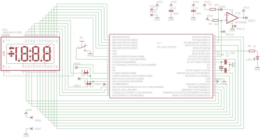
This circuit is centered around the PIC16LF1937 microcontroller, which is essentially a compact computer integrated into a single chip, encompassing RAM, EEPROM, I/O ports, and a CPU. When purchased, the chip is unprogrammed, necessitating the compilation of source code...

The Beckman model W industrial-type pH meter is a direct current (DC) amplifier designed for measuring the potentials generated by pH-sensitive electrodes. The output is capable of driving most recorders. Resistor R32 is utilized exclusively with the 4 to...
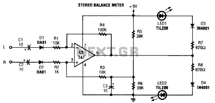
When the L and R signals are equal, no output is present from U1, and pin 6 is at a steady 4.5 V. Unbalanced audio causes the LEDs to vary in brightness, which indicates a difference that corresponds to...
This project is also an essential part of the expandable analyser to be published soon or perhaps eventually, and one meter circuit is used for each frequency band. There are many other uses for a simple LED VU meter....
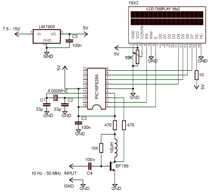
The frequency meter is capable of measuring frequencies ranging from 10 Hz to 60 MHz, with a precision or resolution of 10 Hz. It can be utilized to assess the frequency of various devices such as oscillators, transmitters, frequency...
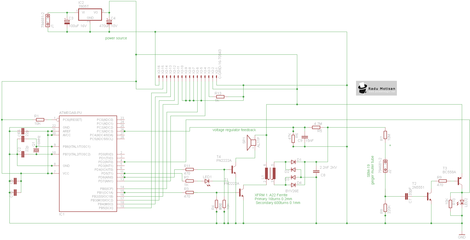
An efficient and stable construction for radiation dosimetry needs. The design centers around the Atmel Atmega8 microcontroller and a Russian Geiger Muller tube, specifically the CTC-1 tube for high gamma doses. The dosimeter is compatible with various tubes including...